
Off-Grid ESP32 Flood-Stage Sensor: Cutting Standby From 20 mA to Under 100 µA on a $70 Solar Node
Full open-hardware build: ultrasonic stage sensing, LiFePO4 pack, and the dev-board parasitic draw that wastes 89% of a node's daily energy.

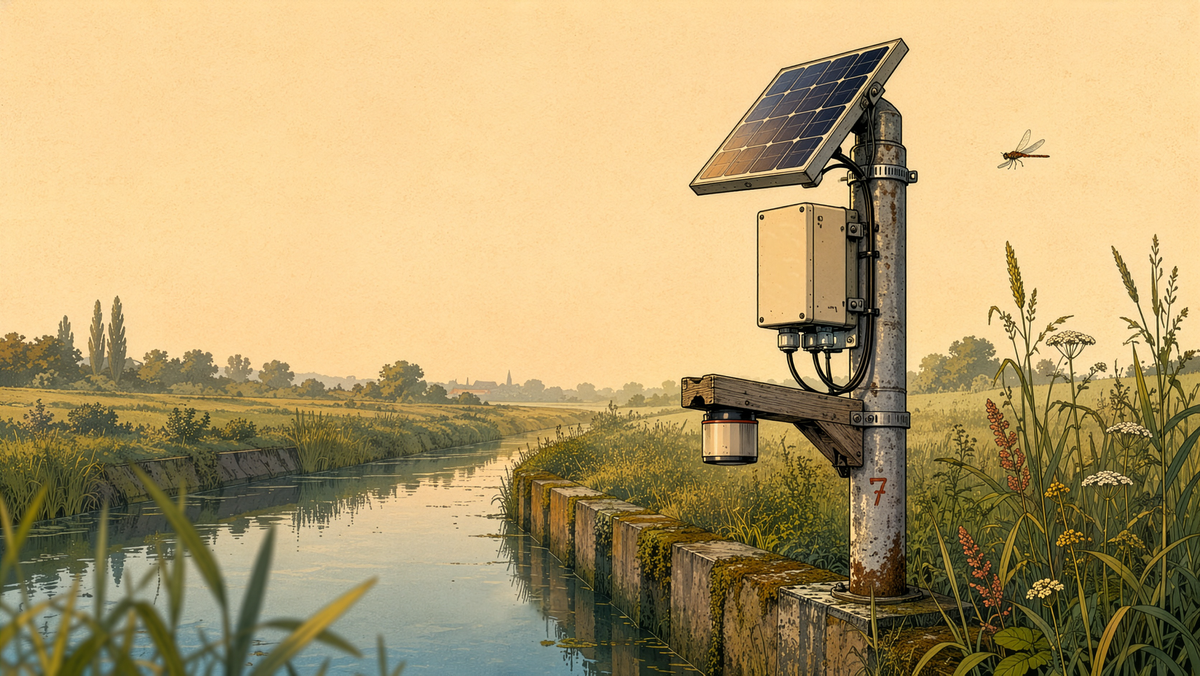
Open-Source Off-Grid Ultrasonic Flood-Stage Monitoring Node
A solar-powered ESP32 sensor pole with sub-milliamp standby, LiFePO4 storage, and four costed low-quiescent-current power topologies.
License: Hardware under CERN-OHL-S v2; documentation under CC BY-SA 4.0. Version: 1.0, 3 August 2026.
Epistemic legend
- [D] Datasheet or manufacturer-specified value.
- [M] Measured, from a named bench or independently published measurement.
- [E] Estimated or modeled; the reasoning is shown.
- [J] Asserted design judgment; justified in text.
TL;DR
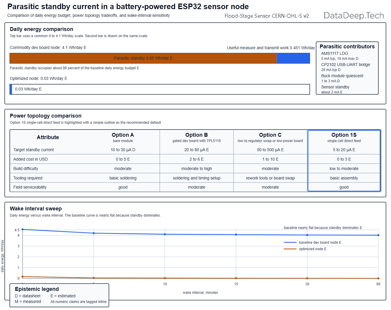
- A reproducible off-grid ultrasonic flood-stage node can be built for about $70 to $95 (cheapest path) versus $960 to $1,200 for the nearest commercial telemetered unit, and the engineering problem is not the sensor but parasitic standby current: on a commodity ESP32 dev board, roughly 89% of the daily energy is wasted by the on-board USB-UART bridge and the AMS1117 regulator, not by useful work.
- Fix the standby term and everything else gets easier. Killing the parasitic draw (bare module + low-Iq regulator (low quiescent current LDO), or a power-gated dev board, or a 1S single-cell direct-feed) drops daily energy from about 4.1 Wh/day to under 0.05 Wh/day, pushes no-sun autonomy from about 17 days to hundreds of days, and lets you shrink from a 50 W panel and 4S pack to a 10 to 20 W panel and a single cell. The recommended default is the 1S single-cell topology, which deletes the entire 12 V-to-3.3 V conversion stage.
- Ultrasonic sensing is "good enough" (a few cm), not regulatory-grade, and it fails predictably. Use a 3.3 V-native UART sensor (A02YYUW) to avoid level-shifting, add mandatory speed-of-sound temperature compensation, filter with N-ping medians, and flag data as low-confidence during rain/foam/multipath. In narrow canals or persistent foam, switch to a MaxBotix narrow-beam sensor or a 24/60 GHz radar.
1. Summary
A fully off-grid, pole-mounted water-level telemetry node that measures distance to the water surface with a downward-facing ultrasonic sensor, converts it to stage height, and posts JSON to an existing endpoint over WiFi, LoRa, or cellular, engineered so that parasitic standby, not useful work, is the design target.
2. At-a-glance box
- Total estimated cost (USD): Cheapest viable path about $70 to $95. Upgrade path about $180 to $260. (Both exclude the commercial radar sensor upgrade; see BOM.) Prices are estimates and vary by region and date.
- Estimated build time: 8 to 16 hours for an intermediate maker, spread over two sessions (one for the pack and electronics, one for the pole and enclosure).
- Difficulty: Intermediate. Cheapest path needs only a soldering iron and a multimeter. Option A (bare module) needs fine-pitch SMD soldering.
- Key tools: soldering iron, multimeter, drill, hacksaw or pipe cutter, screwdrivers, wire strippers, heat-shrink/heat gun. A cheap DC current meter (INA219 or a multimeter in microamp range) is needed for commissioning.
Mission and Objectives
3. Abstract and purpose
This document specifies a reproducible, repairable water-level monitoring node for a flood-prone watercourse, drainage canal, or urban catchment. The node runs unattended 24/7 on solar power. It wakes on a timer, measures the air gap from a fixed datum to the water surface, converts that to stage, timestamps and buffers the reading, transmits it, and returns to deep sleep.
The web dashboard, database, and front end are out of scope. The network is treated only as a transport contract: an HTTP POST or MQTT publish of a JSON payload with an auth token, plus retry and offline-buffer semantics.
Who it is for: off-grid, FOSS-minded builders, community-science flood programs, small municipalities, and researchers who need many nodes at a fraction of commercial telemetered-gauge cost.
Limits, stated up front [J]: ultrasonic ranging is not a universal solution. It degrades in heavy rain, dense fog, foam, floating debris and vegetation, strong temperature stratification over water, and high wind. It is defeated by insects and spiders nesting in the transducer cup. Where these conditions dominate, the node must flag its data as low-confidence, and the builder should consider a 24/60 GHz radar sensor instead (see Sections 4 and 15). This node targets the practical accuracy of low-cost citizen-science gauges (a few centimeters), not the USGS regulatory standard, which per USGS Office of Surface Water Technical Memoranda requires stage equipment "capable of sensing and recording stage with an uncertainty of no more than 0.01 ft or 0.20 percent of indicated reading, whichever is larger" [D, USGS OSW policy] (about 3 mm below 5 ft of effective stage).
4. Design rationale and theory of operation
4.1 Governing physics
Ultrasonic time-of-flight ranging measures the round-trip time t of a 40 kHz pulse and computes distance d = c·t/2, where c is the speed of sound in air. The critical dependency is that c varies strongly with temperature: c = 331.3 + 0.606·T m/s, where T is in degrees C [D, standard acoustics]. That is about 0.6 m/s per degree C. An uncompensated swing of 20 degrees C changes c by about 12 m/s out of about 343 m/s, roughly 3.5% range error [E, from the equation]. At a 3 m (9.8 ft) mounting height that is about 100 mm (3.9 in) of error, which is unacceptable for stage. Temperature compensation is therefore mandatory, not optional [J]. Humidity changes c by only a few tenths of a percent across the full range and is second-order; we ignore it and note the residual [J].
Stage is derived by subtraction: stage = datum_height - measured_air_gap, where datum_height is the fixed vertical distance from the sensor face to the established zero datum, set once at calibration.
4.2 Why this architecture
The single most important finding of this project is that on a commodity ESP32 dev board, the sleeping system is dominated by parasitic loads, not by the microcontroller. The bare ESP32 SoC sleeps at about 10 uA in RTC-timer deep sleep [D, Espressif ESP32 series datasheet] but real dev boards measure 5 to 20 mA in deep sleep [M, multiple independent measurements including grillbaer's ESP32 power-consumption test repository, which measured a NodeMCU ESP-32S at 4.7 mA deep sleep] because the on-board USB-UART bridge and the AMS1117 linear regulator stay powered.
The AMS1117-3.3 alone has a quiescent (ground) current of 5 mA typical, 10 mA maximum [D, Advanced Monolithic Systems AMS1117 datasheet, 6.5 V ≤ VIN ≤ 12 V]. That is roughly 500 to 1,000 times the sleeping SoC. The USB-UART bridge adds to it and, critically, is not commanded into its low-power USB-suspend state during ESP32 deep sleep. Bridge draws in normal operation, from the manufacturer datasheets [D], are:
- CP2102: 20 mA typ, 26 mA max (normal); only 80 to 100 uA in USB suspend [D, Silicon Labs CP2102/9 datasheet].
- CP2102N: 9.5 mA typ (normal); 195 uA suspend [D, Silicon Labs CP2102N datasheet].
- CH340C/CH340G: 7 mA typ, 20 mA max at 5 V (4 mA typ at 3.3 V); 40 to 90 uA suspend [D, WCH CH340 datasheet].
So the widely quoted "25 to 30 mA of parasitic dev-board draw" is accurate specifically for CP2102-based boards (about 20 to 26 mA bridge + about 5 mA AMS1117). For CH340C/CH340G or CP2102N boards it is lower, roughly 12 to 15 mA, but still 1,000+ times the sleeping SoC [E, from the datasheet figures above]. Either way, the dev board's own housekeeping silicon, not the ESP32, sets the standby budget.
Everything in this design follows from attacking that parasitic term. The four power options in Section 4.4 are four ways to kill it. The measurement, radio, and firmware choices all aim to keep the active-energy term small enough that standby, once fixed, dominates the budget in a good way (that is, at microwatts).
4.3 Key parameters and how they were chosen
- Wake interval: default 10 min. Flood stage changes on the order of minutes to hours in most catchments; 10 min is a reasonable compromise between latency and energy. It is a firmware variable (see the parametric model in Section 5), and threshold-driven fast sampling is added for rising water.
- Mounting height: sensor face must sit above maximum expected flood stage plus the sensor dead zone plus margin. See Section 9.
- Storage voltage architecture: the baseline uses a 4S LiFePO4 pack (12.8 V nominal) feeding a buck to 3.3/5 V. We show this is usually the wrong choice for a microwatt load and present a 1S direct-feed alternative as the fourth power option, because eliminating the whole 12 V-to-3.3 V conversion stage is the single biggest efficiency and cost win available [J].
4.4 The four power topologies (summary; full detail in Sections 6 and 10)
- Option A (best performance, hardest build): bare ESP32-WROOM-32E module on protoboard/PCB with a low-Iq regulator (HT7833 or TPS62840). No USB bridge. Programmed via external FTDI + esptool, updated via OTA.
- Option B (moderate, keeps dev board): keep the dev board but hard-gate its power with a TPL5110 nano-timer (35 nA typical, 50 nA max [D, TI TPL5110 datasheet / SparkFun]) driving a P-channel MOSFET, so the board is fully off between samples and cold-boots each cycle.
- Option C (easiest): swap the AMS1117 for a pin-compatible low-Iq LDO, or buy a low-power board (FireBeetle ESP32) whose deep sleep is independently measured near 10 uA [M, Lucidar].
- Option 1S (recommended default) [J]: run the whole node from a single LiFePO4 cell (or 1S Li-ion) directly into a low-Iq 3.3 V regulator, deleting the 4S pack, BMS complexity, buck module, and PWM controller's 12 V penalties.
 jktightwad
5. Specifications, performance targets, and the parametric power budget
5.1 Targets
- Stage measurement range: about 0.3 to 4.5 m (1 to 14.8 ft) air gap depending on sensor.
- Practical field accuracy: plus or minus 2 to 5 cm (0.8 to 2 in) with temperature compensation and N-ping filtering [E, consistent with the UNC COAST Lab deployment which reported 5 cm accuracy and 1.5 cm RMSE against a commercial unit].
- Standby target: under 100 uA system standby (optimized), versus 5 to 20 mA baseline.
- Daily energy target: under 0.5 Wh/day optimized, versus about 4.1 Wh/day baseline.
- Autonomy target: over 100 days of no-sun autonomy on a modest pack.
- Service life: 3 to 8 years, gated by LiFePO4 pack (2000+ cycles at 80% depth of discharge [D]) and UV degradation of enclosure/cabling.
- Duty cycle: active roughly 2 to 5 s per wake; sleeping the rest.
5.2 The parametric power budget (worked model)
Daily energy is:
E_day (Wh) = N_cycles * E_active + P_standby * 24
N_cycles   = 1440 / T_wake            (T_wake in minutes)
E_active   = E_boot + E_sensor + E_assoc + E_tx      (Wh per cycle)
Variables:
T_wake= wake interval (min).E_boot= energy to wake/boot the compute (deep-sleep wake is cheap; cold boot is not).E_sensor= sensor power-on settle + N-ping burst.E_assoc= WiFi association energy (dominant active term; cold DHCP scan is several seconds, pinned BSSID/channel/static IP is about 1 s).E_tx= transmit + ACK.P_standby= continuous standby power (the parasitic term).
Baseline (dev board, 4S, PWM, cheap buck, HC-SR04) [E, built from measured/datasheet component draws]:
- Parasitic standby: dev-board bridge+LDO about 25 to 30 mA at 5 V, buck quiescent 1 to 3 mA at 12 V, HC-SR04 standby about 2 mA. Referred to 12 V this is about 283 mAh/day, roughly 3.4 Wh/day, or
P_standbyabout 0.142 W. - Active: about 0.0028 Wh/cycle (ESP32 TX peak about 240 mA at 3.3 V [D], association about 1 to 3 s).
- At
T_wake= 10 min: E_day = 144 * 0.0028 + 3.4 = 0.40 + 3.4 = about 3.8 Wh/day. About 4.1 Wh/day including BMS/controller overhead. 89% is parasitic standby.
Optimized (Option A or 1S, bare module + HT7833/TPS62840, power-gated A02YYUW) [E]:
P_standby: ESP32 10 uA [D] + regulator about 4 uA [D, HT7833 low-Iq clone variant; note datasheet-vs-marketing conflict below] + BMS/leakage, call it about 40 uA at 3.3 V, about 0.00013 W, about 0.0032 Wh/day.E_active: about 0.2 mWh/cycle with pinned WiFi (E_sensor about 0.04, E_assoc about 0.11, E_tx about 0.04, E_boot about 0.01 mWh).- At
T_wake= 10 min: E_day = 144 * 0.0002 + 0.0032 = 0.029 + 0.003 = about 0.032 Wh/day.
Datasheet-vs-marketing conflict to flag [D/M]: the Holtek HT78xx series datasheet specifies quiescent current of 4 to 5 mA typical [D, Holtek HT78xx datasheet], but many LCSC/AliExpress "HT7833" clone listings claim 2 uA quiescent. These cannot both be the same part. The truly microamp-class low-Iq options with firm datasheet backing are the TPS62840 (60 nA typ Iq, 750 mA, 80% efficiency at 1 uA load [D, TI TPS62840 datasheet]), MCP1700 (about 2 uA [D]), XC6206/XC6203 class, and ME6211. Verify the actual Iq of whatever "HT7833" you receive on the bench before trusting it; if it measures milliamps, treat it as a standard LDO and substitute a TPS62840 or MCP1700 for the optimized build [J].
5.3 Wake-interval sweep (Wh/day and autonomy)
Autonomy uses 66.6 Wh usable for the 4S pack and 15.4 Wh usable for a single-cell 1S pack (one 32650 at about 19.2 Wh gross, 80% depth of discharge). Values are modeled [E]; verify on the bench (Section 11).
| T_wake (min) | Cycles/day | Baseline Wh/day | Baseline autonomy (4S) | Optimized Wh/day | Optimized autonomy (1S) |
|---|---|---|---|---|---|
| 1 | 1440 | 7.4 | 9 d | 0.29 | 53 d |
| 5 | 288 | 4.2 | 16 d | 0.060 | 257 d |
| 10 | 144 | 3.8 | 17 d | 0.032 | 480 d |
| 15 | 96 | 3.7 | 18 d | 0.021 | 730 d |
| 30 | 48 | 3.5 | 19 d | 0.012 | 1280 d |
| 60 | 24 | 3.5 | 19 d | 0.007 | 2200 d |
Two lessons are visible [J]: (1) on the baseline, changing the wake interval barely moves the daily energy because standby dominates, so optimizing firmware timing on an un-fixed dev board is wasted effort; (2) once standby is fixed, autonomy far exceeds the self-discharge and calendar-life limits of the pack, so the pack can be shrunk drastically, which is the real cost win. (The multi-hundred-day "autonomy" figures are model ceilings; in practice self-discharge and BMS leakage cap useful autonomy at weeks to a few months, which is still far beyond any realistic monsoon overcast.)
6. Bill of Materials
Prices are indicative USD street prices from generic online marketplaces (AliExpress/Amazon/eBay class) or distributors (LCSC/Mouser/DigiKey) as noted; all are estimates and vary by region and date.
6.1 Core node (shared across options)
| # | Item | Spec/size | Qty | Generic name (or model + why) | Est. unit (USD) | Line total | Source / notes | Salvage alt. |
|---|---|---|---|---|---|---|---|---|
| 1 | Ultrasonic sensor | UART, 3.3 V, IP67 | 1 | A02YYUW / SEN0311 (natively 3.3 V-safe UART, no level shifter) | 16 | 16 | DFRobot direct $15.90 [D]; generic clones cheaper | HC-SR04 from junk drawer (needs level shifter, not waterproof) |
| 2 | Temp sensor | 1-wire | 1 | DS18B20 waterproof probe | 2 | 2 | generic | salvage from old thermostat |
| 3 | Compute | ESP32 module/board | 1 | See per-option table 6.3 | 3 to 12 | 3 to 12 | generic | salvage dev board |
| 4 | Regulator | 3.3 V low-Iq | 1 | TPS62840 (60 nA [D]) or MCP1700 (2 uA [D]) | 0.30 to 3 | 0.30 to 3 | LCSC/Mouser | none |
| 5 | RTC/timer (Option B) | nano-timer | 1 | TPL5110 breakout (35 nA typ [D]) | 5 | 5 | SparkFun/Adafruit/generic | none |
| 6 | Enclosure | IP65/66 polycarbonate, UV-stable, light color | 1 | 150 x 100 x 70 mm gland box | 8 | 8 | hardware store | food container + sealant (lower IP) |
| 7 | Pressure vent | breathable membrane vent, M12 | 1 | Gore-type vent or generic | 2 | 2 | generic | Gore-Tex patch + epoxy |
| 8 | Cable glands | PG7/PG9 for cable OD | 2 to 3 | nylon glands | 0.50 | 1.50 | hardware store | rubber grommet + sealant |
| 9 | Desiccant | silica gel, indicating | 1 | 10 to 20 g sachet | 1 | 1 | generic | rice (poor, temporary) |
| 10 | Surge/TVS | SMAJ series TVS + MOV | 3 | TVS diodes on panel + sensor leads | 0.30 | 1 | LCSC | none |
| 11 | Inline fuse | 1 to 3 A + holder | 1 | automotive blade fuse | 1 | 1 | auto store | salvage |
| 12 | Wire, heat-shrink, connectors | assorted | 1 | silicone hookup wire, JST | 4 | 4 | generic | salvage |
6.2 Power generation and storage
| # | Item | Spec/size | Qty | Generic name | Est. unit | Line total | Source / notes | Salvage alt. |
|---|---|---|---|---|---|---|---|---|
| 13 | Solar panel | 10 to 20 W mono (optimized) or 50 W (baseline) | 1 | monocrystalline panel | 12 to 40 | 12 to 40 | generic | salvaged garden-light or caravan panel |
| 14a | Cells (1S path) | 32650/32700 LiFePO4, 6 Ah | 1 | LiFePO4 cell | 4 | 4 | BatteryHookup double-tested 6000 mAh [M] | salvage LiFePO4 from solar lights |
| 14b | Cells (4S path) | 32650/32700 LiFePO4, 6 Ah | 4 | LiFePO4 cell | 4 | 16 | generic | as above |
| 15 | BMS | 1S or 4S LiFePO4, low-temp cutoff | 1 | protection board | 2 to 8 | 2 to 8 | generic; confirm <0 C charge inhibit | none (do not omit) |
| 16 | Charge control | MPPT (upgrade) or PWM LiFePO4-capable | 1 | solar charge controller | 6 to 25 | 6 to 25 | generic | none |
| 17 | Cell holders / nickel strip | 32650 holders or 0.15 x 8 mm strip | 1 | holders (no-weld) | 2 | 2 | generic | salvage strip |
| 18 | Pole + mount | 40 to 50 mm galvanized pipe, U-bolts, bracket | 1 | pipe + fittings | 15 | 15 | hardware store | salvaged pipe/fence post |
6.3 Per-option compute and regulation
| Option | Key parts | Added cost | Standby (target) | Build difficulty |
|---|---|---|---|---|
| A | ESP32-WROOM-32E module (~$3), TPS62840 board (~$3) or MCP1700 (~$0.30), FTDI for programming | 6 to 10 | about 15 to 40 uA | Hard (SMD) |
| B | NodeMCU-32S dev board (~$5) + TPL5110 (~$5) + P-MOSFET (~$0.30) | 10 | about 20 to 60 uA (timer + off board) | Easy to moderate |
| C | FireBeetle ESP32 DFR0478 (~$8), or AMS1117 desolder + low-Iq LDO | 4 to 8 | about 10 uA (FireBeetle) [M, Lucidar] | Moderate (desolder) |
| 1S | Any bare module + TPS62840/MCP1700, single cell, 1S BMS, small panel | 6 to 9 | about 30 to 50 uA | Moderate |
6.4 Cost summary
- Cheapest viable path (1S, salvaged pole, PWM, A02YYUW, generic box): about $70 to $95.
- Upgrade path (Option A bare module, MPPT, larger enclosure with quality vent, surge suite, LoRa or cellular radio): about $180 to $260.
- Commercial radar sensor upgrade (if ultrasonic is inadequate): add $300 to $900 for the sensor alone.
7. Tools and equipment
| Tool | Category | Est. cost if bought | Manual fallback |
|---|---|---|---|
| Soldering iron | Likely owned | 15 to 40 | none; borrow from makerspace |
| Multimeter (with uA range) | Likely owned | 15 to 40 | borrow; needed for commissioning |
| Drill + bits | Likely owned | 30 | hand brace and bit |
| Hacksaw / pipe cutter | Likely owned | 15 | hand hacksaw |
| Wire strippers, screwdrivers | Likely owned | 10 | knife (careful) |
| Heat gun | Likely owned | 15 | lighter (careful with shrink) |
| INA219 module or uCurrent | Borrow/buy | 3 (INA219) to 60 (uCurrent) | shunt resistor + DMM |
| Nordic PPK2 or Otii Arc | Borrow/rent | 100 to 500 | supercap discharge method |
| Hot-air rework (Option A/C SMD) | Borrow/rent | 40 | fine iron + drag soldering |
| Spot welder (only if welding pack) | Borrow/rent | 50+ | use cell holders instead (no weld) |
8. Skills and safety
Required competencies: basic soldering (fine-pitch for Option A/C), safe use of a drill and saw, multimeter use including current measurement, and following a wiring diagram.
Hazards specific to this build:
- Stored energy / lithium cells: LiFePO4 is the safest common lithium chemistry but a shorted 6 Ah cell delivers tens of amps (max continuous discharge is typically 3C, about 18 A [D, BatteryHookup 32650 spec]) and can burn or start a fire. Never short terminals, always fuse the pack, and never solder directly to cell cans (heat damages the cell and can vent it). Use spot welding or cell holders.
- Cold-charging damage: charging LiFePO4 below 0 degrees C causes lithium plating, permanent capacity loss, and a latent short risk. The BMS must inhibit charge below 0 degrees C (set a 5 degrees C buffer) [D; REDARC tech note states charging below 0 degrees C "must be avoided" and gives an optimum charge window of 5 to 45 degrees C].
- Working at height / over water: deploying on a bank or bridge over moving water is a drowning and fall hazard. Use a harness/tether and a second person. Do not deploy in active flood.
- Electrical: this is a low-voltage DC system, but the solar panel is a live source in daylight; cover it during wiring.
- Sharp edges: cut pipe and drilled enclosures have burrs.
PPE: eye protection (drilling, cutting, soldering), gloves for pipe work, fume extraction or ventilation for soldering.
Lockout / safe handling: before working on wiring, disconnect the panel first, then the battery; reconnect battery first, panel last. No bulk capacitors need discharging, but treat the pack as always live.
Codes and standards to check locally [J, builder must verify]: any permit to install structures in or over a watercourse; electrical/grounding codes for outdoor DC and pole earthing; radio spectrum rules if using LoRa (ISM band and duty-cycle limits differ by region) or cellular (approved modem/SIM). Battery shipping/transport is regulated (UN38.3, Class 9).
9. Build instructions
Phase 1: Verify and match cells (BOM 14)
- Charge each 32650 cell individually to 3.65 V and rest. Discharge-test capacity with a cheap capacity tester (for example a generic USB/DC electronic load). Do not trust the printed capacity; "6000 mAh" 32650/32700 cells are commonly overstated, and many cells sold as "32650" are physically the taller 32700 [M, multiple vendor listings note "the actual cell size is 32700, not 32650"]. Reject any cell more than 5% below the group.
- Go/no-go: all cells within 5% capacity and matched resting voltage before assembly.
Phase 2: Build the pack (BOM 14 to 17)
- For 1S (recommended): one matched cell into a holder, BMS soldered to holder tabs (not the cell), then to the load. For 4S: four cells in series in holders; size nickel strip or wire for the peak load (a few amps is plenty here; 0.15 x 8 mm nickel handles about 5 A). Add compression/restraint so cells cannot move.
- Install the inline fuse (BOM 11) on the pack positive lead, close to the cell.
- Go/no-go: pack voltage correct (about 3.3 V for 1S, about 13.2 V for 4S at full charge), BMS cutoffs verified by gently loading/charging.
Phase 3: Build the compute and power board (per chosen option)
- Option A: solder the ESP32-WROOM-32E to protoboard/PCB, add the low-Iq regulator with 1 to 10 uF ceramics on VIN and VOUT close to the pins, bring out an FTDI header (TX, RX, EN, GPIO0, GND, 3V3).
Option B: wire the TPL5110 DRV to the gate of a P-MOSFET high-side switch feeding the dev board 5 V input; wire DONE to a spare GPIO; set the delay resistor for the wake interval (REXT between 500 ohm and 170 kohm sets 100 ms to 7200 s [D, TI TPL5110 datasheet]).
Option C: desolder AMS1117 with hot air, fit a pin-compatible low-Iq LDO, or just use a FireBeetle. - Wire the A02YYUW: VCC to 3.3 V, GND, TX to an ESP32 UART RX. Because the A02YYUW is spec'd for 3.3 to 5 V operation with matching logic tolerance [D, DFRobot SEN0311 datasheet], powering it at 3.3 V makes its UART TX swing 0 to 3.3 V, so no level shifter is required. If instead you use an HC-SR04 or JSN-SR04T, the 5 V ECHO pin must be dropped to 3.3 V with a divider (for example 1 kohm series and 2 kohm to ground) or a level-shifter IC before the GPIO.
- Wire the DS18B20 (BOM 2) with a 4.7 kohm pull-up on the data line.
- Add TVS diodes (BOM 10) across the panel input and across the sensor supply/signal lines.
- Go/no-go: flash firmware, confirm a clean sensor reading and a WiFi/LoRa transmit on the bench.
Phase 4: Measure standby (critical acceptance gate)
- With firmware in deep sleep, measure standby current (Section 11). Do not proceed until you have hit your target (well under 1 mA, ideally under 100 uA). This is the make-or-break step [J].

Phase 5: Mount sensor, enclosure, panel, pole
- Mount the A02YYUW pointing straight down through a gland or a short length of PVC pipe as a baffle. Keep the transducer face clear; add a coarse insect screen that does not block the beam.
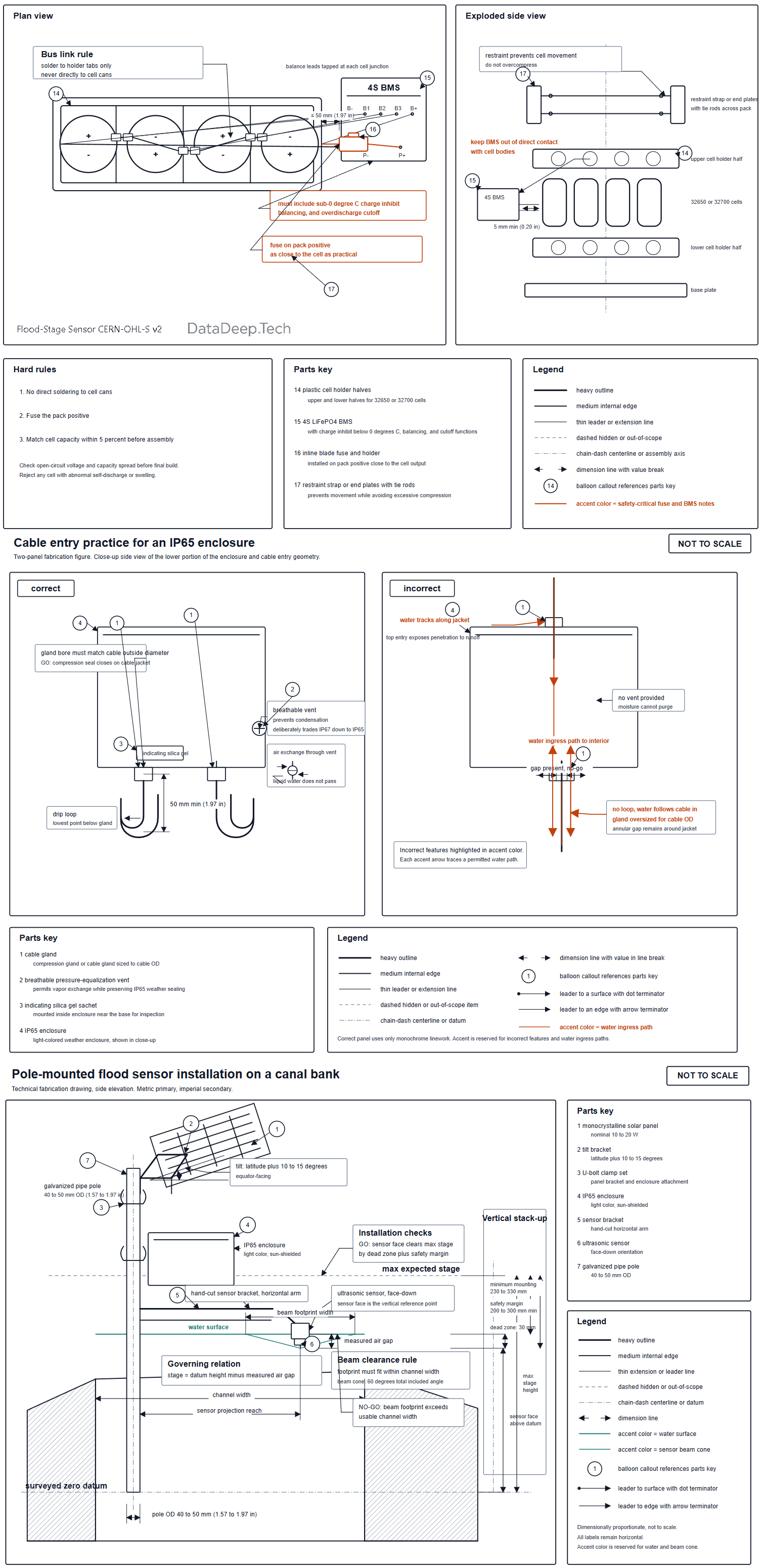
- Fit the enclosure with the breathable vent at the bottom or side (see Section 12 for the IP tradeoff), cable glands sized to the actual cable OD, and drip loops on every cable entering the box.
- Mount the panel tilted (latitude plus about 10 to 15 degrees for winter/monsoon bias) and steeply enough to self-shed dust and debris; face equator-ward. Use tamper-resistant fasteners for anti-theft.
- Set mounting height: sensor face above maximum expected stage + sensor dead zone (A02YYUW 3 cm [D]) + at least 20 to 30 cm margin.
- Earth/ground the metal pole per local practice; keep the electronics ground referenced sensibly and use the TVS suite for surge.
- Go/no-go: full end-to-end reading transmitted, datum calibrated (Section 11), enclosure sealed with desiccant inside.
Figure captions:
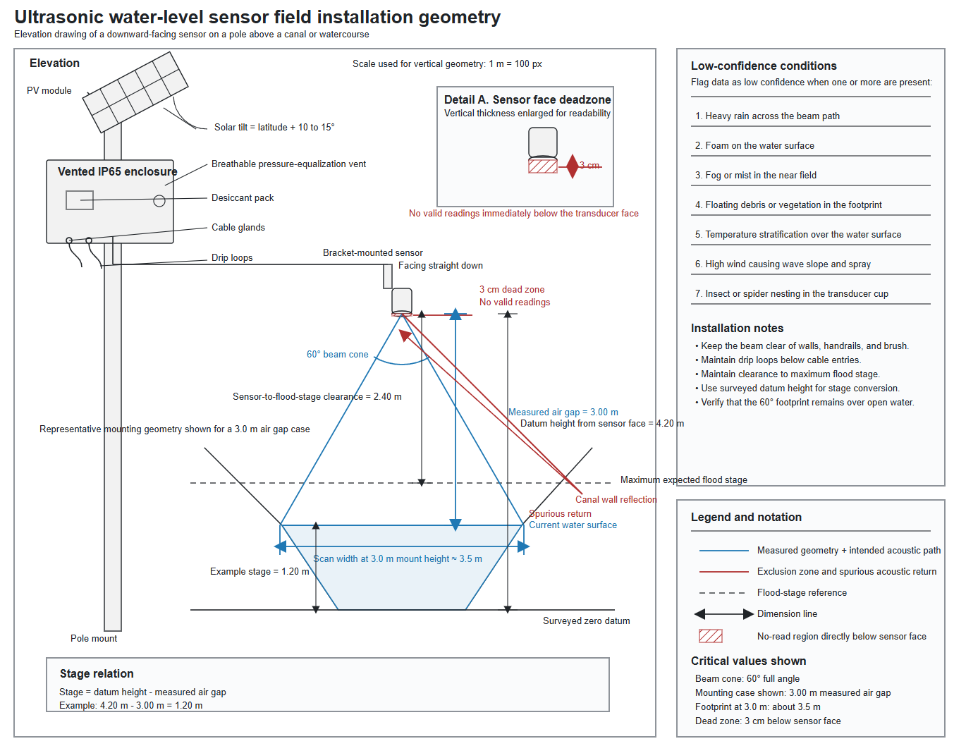
- Figure 9.1: Elevation of pole, panel (with tilt angle), enclosure, and downward sensor, showing sensor height above max stage.
- Figure 9.2: Close-up of enclosure entries showing drip loops, glands, and vent placement.
- Figure 9.3: Pack assembly showing holders, fuse position, BMS, and restraint.
10. Drawings and schematics
Recommended free tools: FreeCAD (mechanical, exploded view), KiCad (Option A PCB and schematics), LibreCAD (2D fab drawings), Inkscape (signage, wiring diagrams).
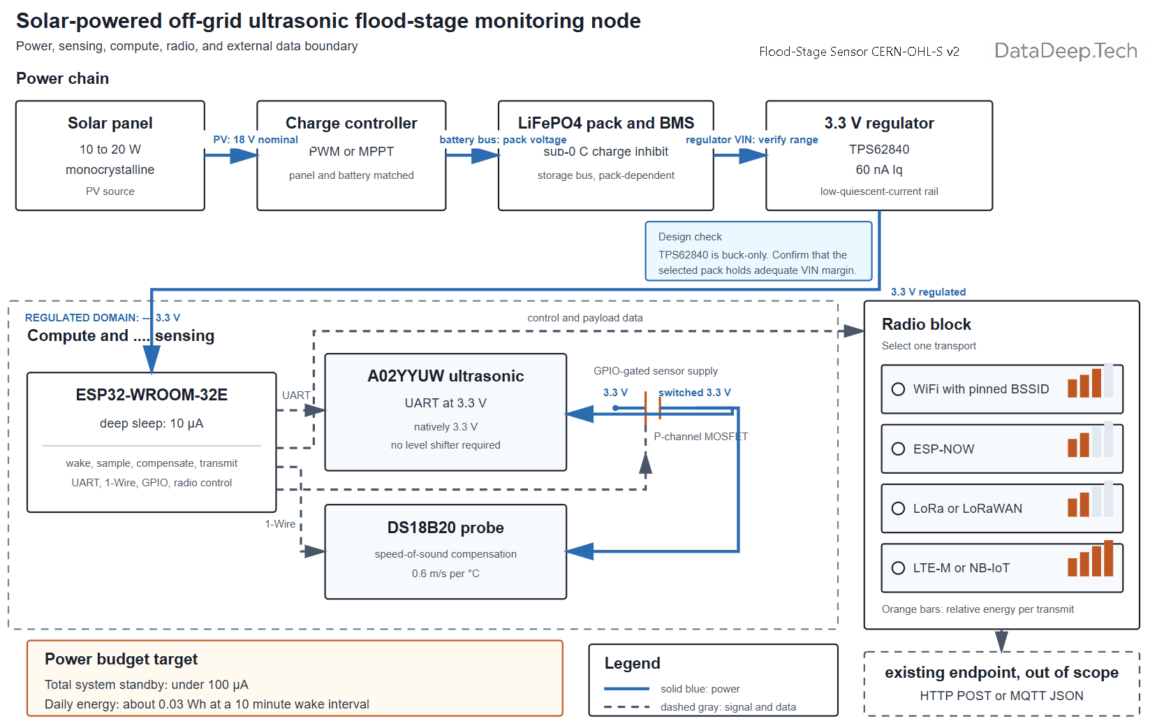
10.1 System block diagram (ASCII)
 [Solar panel 10-20W] --+--> [Charge controller: MPPT or PWM]
                        |            |
                     [TVS]        [LiFePO4 pack + BMS w/ <0C charge inhibit]
                                     |
                              [Low-Iq 3.3V regulator]  (1S: direct; 4S: buck first)
                                     |
        +----------------------------+----------------------------+
        |                            |                            |
   [ESP32 module]             [A02YYUW UART 3.3V]           [DS18B20 temp]
   deep-sleep timer          (power-gated GPIO)             (speed-of-sound comp)
        |
   [Radio: WiFi / LoRa / LTE-M] --> existing endpoint (HTTP POST / MQTT)
10.2 Power topology A (bare module + low-Iq regulator)
 Vbat(3.3-4.2 1S / 12.8 4S) -> [TPS62840 / MCP1700] -> 3V3 -> ESP32-WROOM-32E
                                              |-> gated 3V3 -> A02YYUW (via GPIO+P-FET)
 Programming: FTDI header (TX/RX/EN/IO0/GND) ; Updates: ArduinoOTA + rollback
 Standby: ESP32 ~10uA [D] + reg 60nA-2uA [D]  => target 15-40uA [E]
10.3 Power topology B (gated dev board + TPL5110)
 Vbat -> [TPL5110 Vdd]            (timer Iq 35nA typ / 50nA max [D])
 TPL5110 DRV -> gate of P-MOSFET high-side switch
 P-MOSFET -> dev board 5V input (whole board incl. AMS1117+bridge powered ONLY when on)
 dev board GPIO -> TPL5110 DONE (signals "task complete, cut power")
 Cold boot each cycle: adds E_boot; justified only because off-state ~ tens of uA [E]
10.4 Power topology C (low-Iq swap / low-power board)
 Vbat -> FireBeetle ESP32 (measured ~10uA deep sleep [M, Lucidar]) -> 3V3 rail
 OR: desolder AMS1117, fit pin-compatible low-Iq LDO
 Watch: some boards keep RGB LED / fuel gauge / bridge alive; verify by measurement
 (Lucidar measured FireBeetle DFR0654 at 520uA and a Firebeetle 2 ESP32-E user saw 468uA
  until the low-power pad was cut and BT/ADC disabled - always verify the specific board)
10.5 Mounting geometry (ASCII)
   sensor face  ___[A02YYUW]___     <- fixed to bracket on pole
        |  \        |        /  |     dead zone (3 cm A02YYUW [D]) : NO valid reads
        |   \       |       /   |
        |    \  beam cone 60 deg /   <- footprint must fit inside channel width,
        |     \     |     /     |       avoid canal walls (multipath)
   air_gap (measured)  |
        |              v
  ======================================  <- water surface (moving target)
        |  stage = datum_height - air_gap
   -----+------------------------------  <- zero datum (surveyed once)
Beam-cone note [J]: the A02YYUW's 60 degree reference cone [D] at 3 m gives a footprint about 3.5 m wide, which will hit the walls of a narrow canal and cause spurious near returns. In narrow channels prefer a narrow-beam sensor (MaxBotix MB7389, factory-calibrated narrow beam) or add a baffle tube.
11. Testing, calibration, and validation
11.1 Pre-first-use safety checks
- Confirm fuse present and correct rating.
- Confirm BMS cutoffs (over-charge, over-discharge, and low-temp charge inhibit) by test.
- Confirm no reverse polarity from panel; TVS installed.
11.2 Standby current validation (the key acceptance test)
Named instruments and what each can and cannot resolve:
- INA219 (about $3): convenient I2C, but its resolution floor (about 100 uA with the common 0.1 ohm shunt) is too coarse to trust microamp sleep readings. Good for active current, poor for standby.
- uCurrent Gold (about $60): analog current adapter, resolves down to nanoamps into a DMM; excellent for sleep current. (An ESP32.com user used a uCurrent Gold to measure 31 uA on a stripped-down custom ESP32 board [M].)
- Nordic PPK2 (about $100): measures nA to A and logs waveforms; ideal for capturing the whole wake/TX/sleep cycle and integrating energy per cycle.
- Otii Arc (several hundred USD): power supply plus high-resolution analyzer; best-in-class but expensive.
- Cheap fallback #1: DMM in microamp range in series with the load (only valid at true steady sleep; the burden voltage disturbs active peaks).
- Cheap fallback #2 (supercapacitor method): power the sleeping node from a known supercap, measure the voltage droop over time, compute I = C·dV/dt. Slow but requires no special gear.
Acceptance: measured sleep current within a factor of about 2 of the modeled value. If it is milliamps, something (bridge, LED, LDO, ungated sensor) is still powered; fix before deploying.
11.3 Functional acceptance
- Sensor reads a known distance within a few cm after temperature compensation.
- N-ping median rejects a hand waved through the beam (debris simulation).
- Transmit succeeds; on forced network loss, records buffer and backfill on reconnect.
11.4 Datum calibration
- With the node mounted, physically measure the true water surface (staff gauge or tape) and the node's reported air gap simultaneously.
- Compute and store
datum_heightso reported stage matches the reference. - Repeat at two or three water levels if possible to check linearity.
- Store calibration in RTC memory/flash so it survives sleep and reboot.
12. Operation
- Correct use: downward-facing over reasonably open water within the sensor range; temperature probe shaded and ventilated, not in direct sun.
- Do: keep the transducer face clean; keep the panel unshaded; check the desiccant indicator periodically.
- Do not: point across a narrow canal (multipath); mount where foam or vegetation collects; rely on a single ping.
- Operating envelope: sensor operating temperature roughly -15 to +60 degrees C for the A02YYUW [D]; LiFePO4 charge only above 0 degrees C [D]; discharge is fine well below freezing (down to about -20 degrees C with reduced capacity [D]).
- Thermal caution for a sun-exposed box [E/M]: solar gain can add 11 to 28 degrees C (20 to 50 degrees F) to a sealed enclosure's interior, and a dark box in sun can run 15 to 20 degrees C above a light one; measured side-by-side tests show up to an 18 degrees C difference between dark and light enclosures [M, nVent/Hoffman and industry data]. Since LiFePO4 life degrades at sustained high temperature and charging must stop above the pack's high limit, use a light-colored enclosure and, if possible, a sun shield; a top shield alone cut interior rise by about 25 to 46% in Hoffman's tests [M].
- IP-vs-vent tradeoff [J]: an IP67 box with a breathable vent is no longer IP67; it is deliberately traded down to prevent the daily pressure/temperature cycling that pumps humid air in and condenses water on the electronics. A vented IP65-class box with desiccant and drip loops is more reliable in the field than a "sealed" box that breathes through its weakest gasket.
13 and 14. Maintenance and Troubleshooting
| Interval / Symptom | Task / Likely cause | Consumable, wear part, or fix | Est. cost (USD) |
|---|---|---|---|
| Maintenance | |||
| Monthly (remote check) | Confirm data are arriving and check the battery-voltage trend | None | 0 |
| Quarterly (site visit) | Clean the transducer face and solar panel; check the insect screen; inspect cable glands and drip loops | None | 0 |
| Quarterly | Check and replace the desiccant as required | Silica gel | 1 |
| Annually | Verify the datum against the staff gauge; re-torque mounts; inspect cabling for UV cracking | Zip ties and wire | 2 |
| Every 2 to 4 years | Assess battery-pack capacity and replace cells if capacity fade limits system autonomy | LiFePO4 cells | 4 to 16 |
| As needed | Replace the fuse after a fault | Automotive blade fuse | 1 |
| Troubleshooting | |||
| Sleep current is in mA rather than uA | USB bridge, AMS1117 regulator, status LED, or ungated sensor remains powered | Apply the Option A, B, or C correction; power-gate the sensor; verify current using a uCurrent or PPK2 | — |
| Readings jump or appear noisy | Multipath reflections from canal walls, foam, or floating debris | Add a baffle tube; use a narrow-beam sensor; strengthen the median or trimmed-mean filter | — |
| Transmission is slow and energy-intensive | Cold Wi-Fi association, including scanning and DHCP | Pin the BSSID and channel; assign a static IP address; reduce transmission power | — |
| Reported stage drifts between day and night | Missing or incorrect speed-of-sound temperature compensation | Verify the DS18B20 reading and the temperature-compensation term | — |
| Battery never fully charges during the wet season | Solar panel or battery pack was sized for the annual average rather than the worst-performing month | Resize the power system according to Section 15; increase the interval between wake cycles | — |
| Battery pack is dead after a cold snap | The pack was charged below 0 C, or the BMS lacks a low-temperature cutoff | Install a BMS with low-temperature charge inhibition and insulate the enclosure | — |
| Condensation appears inside the enclosure | The sealed enclosure is breathing through its gasket | Install a breathable pressure-equalization vent and desiccant; add or correct drip loops | — |
| No data are received, but the node remains operational | Endpoint, authentication-token, or retry-handling problem | Check the authentication token, retry backoff, and buffered-data backfill logs | — |
| Intermittent dropouts occur near dawn | Low battery voltage causes a brownout during the transmission-current peak | Add bulk capacitance near the regulator and raise the low-voltage cutoff | — |
15. Variations, scaling, and customization
- Cheaper: 1S single-cell path, salvaged pole and panel, HC-SR04 with a level shifter (accept non-waterproof, short life). Sub-$60 is achievable.
- Larger / higher stage / narrow canals: MaxBotix MB7389 HRXL-MaxSonar-WR (30 to 500 cm, 1 mm resolution, 42 kHz, IP67, 2.7 to 5.5 V, 3.1 mA average / 98 mA peak at 5 V, -40 to +65 degrees C, internal speed-of-sound temperature compensation, narrow factory-calibrated beam [D]) for tall mounts and narrow canals; it is the sensor FloodNet uses.
- Motorized / electrified: not applicable; this is a static sensor. The equivalent "scaling" is a multi-node network (below).
- Multi-pole network: use ESP-NOW between poles to a single uplink node, or LoRa/LoRaWAN to a gateway (the FloodNet approach), to avoid per-node WiFi/cellular.
- Regionally adapted (tropical monsoon): flood events coincide with multi-day overcast, so size the array to the worst-month, not annual-average, irradiance and assume overcast output is only about 10 to 25% of rated [E, consistent with off-grid practice]. Longer autonomy (5+ cloudy days) is essential.
- Regionally adapted (temperate, about 45 N): winter is the binding constraint (December peak-sun-hours can fall to about 1 to 1.5 h/day at northern latitudes [M, PVGIS/off-grid practice]); tilt steeply for snow shedding and to catch low sun, insulate the pack, and rely on the low-temp charge inhibit.
- When to abandon ultrasonic and use radar [J]: if the site has persistent foam, heavy spray, dense fog, or narrow walls causing multipath, a 24/60 GHz radar level sensor is worth the extra cost. Radar is unaffected by air temperature and rain to first order and is what USGS uses for non-contact stage; USGS lab-tested radar stage sensors met the plus or minus 0.01 ft OSW standard [M, USGS OFR 2017-1085].
15.1 Radio link comparison (energy and decision rule)
| Link | Energy per TX (relative) | Range | Recurring cost | Best when |
|---|---|---|---|---|
| WiFi, cold association | High (association dominates; about 3 s scan+DHCP [M]) | AP-local (tens of m) | none | AP already on site |
| WiFi, pinned BSSID/channel/static IP | Medium (about 1 s connect) | AP-local | none | AP on site, want low energy |
| ESP-NOW | Low (no association) | tens to ~200 m | none | multi-pole mesh to one uplink |
| LoRa (SX1276/SX1262, RFM95W) | Low per byte, longer airtime at high SF (latency about 3 s observed [M]) | km-class | none (own gateway) or TTN | remote site, no AP, own/ TTN gateway |
| LoRaWAN via TTN | Low | km-class | free/community | community networks (FloodNet uses this) |
| LTE-M / NB-IoT (SIM7080G, BG95-M3) | Highest (modem attach energy) | anywhere with coverage | SIM/data plan | no local infra, can pay recurring |
Decision rule [J]: if an AP is within range, use pinned WiFi. If not and you control multiple poles, use ESP-NOW to a single WiFi/cellular uplink. If the site is isolated, use LoRa/LoRaWAN to a gateway. Use cellular only when nothing else reaches and you accept a recurring bill and the modem's attach-energy penalty.
15.2 Sensor comparison
| Sensor | Beam / dead zone | Max range | IP | Supply | Current | Temp comp | Output | 3.3 V-safe? | Price (USD) |
|---|---|---|---|---|---|---|---|---|---|
| HC-SR04 | ~15 deg / ~2 cm | ~4 m | none | 5 V | ~2 mA standby [D] | none | trig/echo (5 V) | No (level shift) | 1 to 2 |
| JSN-SR04T v3.0 | ~50 to 70 deg / 25 cm | ~4.5 to 6 m | probe waterproof | 5 V | 5 mA static, 30 mA active [D] | none | trig/echo, UART modes | No (5 V echo) | 3 to 6 |
| A02YYUW / SEN0311 | 60 deg / 3 cm [D] | 4.5 m [D] | IP67 [D] | 3.3 to 5 V [D] | <8 mA avg, ~5 mA standby [D] | none | UART 9600, mm [D] | Yes (native) | ~16 |
| MaxBotix MB7389 | narrow / 30 cm | 5 m [D] | IP67 [D] | 2.7 to 5.5 V [D] | 3.1 mA avg, 98 mA peak [D] | internal [D] | PWM/analog/TTL | Yes (at 3.3 V supply) | ~100 |
| 24/60 GHz radar | narrow | 10+ m | IP66/67 | varies | varies | n/a (unaffected) | analog/SDI-12/serial | varies | 300 to 900+ |
15.3 PWM vs MPPT and the 1S insight [J]
An 18 V Vmp panel on a PWM controller charging a 12.8 V LiFePO4 bank is clamped to about 14.4 V, wasting roughly 20 to 30% of available power (the widely cited PWM-vs-MPPT loss for a mismatched panel [M, off-grid practice]).
MPPT recovers it but costs more and has its own quiescent draw. For a microwatt load, however, the cleanest answer is often neither: run 1S and delete the 12 V stage entirely.
A single LiFePO4 cell charged by a tiny 1S solar charge board feeding a low-Iq 3.3 V regulator removes the buck's multi-milliamp quiescent penalty (measured examples: MP1584 about 493 uA, LM2596 about 4.9 mA, versus TPS62840 at 60 nA [M, Pallav Aggarwal bench measurements; D, TI]), the PWM clamp loss, and most of the BMS complexity at once. This is the recommended default for a single node. LiFePO4 charge parameters remain: 14.4 to 14.6 V absorption for 4S (3.6 to 3.65 V per cell), 13.6 to 13.8 V float or no float, and never lead-acid equalization [D, standard LiFePO4 charging].
15.4 Firmware pseudocode (sleep/wake/measure/transmit, ring buffer, retry/backoff)
on_wake():
    load calibration + seq_counter from RTC_memory
    T = read_DS18B20()
    c = 331.3 + 0.606*T
    samples = []
    power_on(sensor_gpio); settle(60 ms)
    for i in 1..N_PINGS:                 # N_PINGS e.g. 7
        d = read_A02YYUW_UART()          # already mm, temp not compensated internally
        d = d * (c / c_ref)              # apply speed-of-sound correction
        samples.append(d)
    power_off(sensor_gpio)
    air_gap = trimmed_mean(reject_outliers(samples))
    valid = within_range(air_gap) and dispersion(samples) < LIMIT
    stage = datum_height - air_gap
    record = {seq, ts, stage, air_gap, T, valid, vbatt}
    push_ring_buffer(record)             # RTC RAM or flash

    if wifi_connect_pinned(bssid, chan, static_ip, timeout=5s):
        while ring_buffer not empty:
            r = peek()
            if POST(endpoint, token, json(r)) == 2xx: pop()
            else: break                  # keep for next time
        reset_backoff()
    else:
        n = increment_backoff()
        sleep_extra = min(BASE << n, BACKOFF_MAX)   # exponential backoff

    seq_counter += 1
    save(calibration, seq_counter) to RTC_memory
    if stage > THRESHOLD_HI + HYST: T_wake = FAST_INTERVAL   # rising-water fast mode
    elif stage < THRESHOLD_HI - HYST: T_wake = NORMAL_INTERVAL
    feed_watchdog()
    deep_sleep(T_wake + sleep_extra)
JSON payload schema:
{ "id":"node-07", "seq":1234, "ts":"2026-08-02T14:30:00Z",
  "stage_m":1.83, "air_gap_m":1.17, "temp_c":27.4,
  "vbatt_v":3.31, "valid":true, "rssi":-71, "fw":"1.0" }
Transport contract: HTTP POST JSON with Authorization: Bearer <token>, expect 2xx to dequeue, else retain and back off. MQTT publish to flood/<id>/stage with token as username/password or TLS client cert, QoS 1, retain off; buffered records replayed oldest-first on reconnect. Watchdog (hardware + software), brownout detection, and OTA-with-rollback are enabled; if OTA fails, the bootloader reverts to the last good partition and a physical FTDI header is the field recovery path.
16. Cost analysis
- This build: cheapest path about $70 to $95; upgrade path about $180 to $260.
- Nearest commercial equivalents: turnkey telemetered ultrasonic/hydrostatic water-level units are commonly $960 to $1,200 per node (for example EnviroNode/INCYT ultrasonic and hydrostatic beacons list at $960 to $1,200 [D, agtech.dpi.nsw.gov.au catalog]), and research-grade radar stage sensors plus a Campbell Scientific-class datalogger run well into the thousands. Community-science DIY designs land near $100 to $210 per unit (UNC/COAST Lab about $100 [M, Bresnahan et al. 2023]; FloodNet under $200 for the sensor, about $210 with mounting hardware [D, FloodNet BOM]).
- Payback / cost-per-use: against a $1,000 commercial node, the cheapest build recovers its cost immediately and roughly 10x on unit count; a 10-node community network costs about $700 to $2,600 in parts versus roughly $10,000 commercial. Cost-per-reading is dominated by the one-time build; energy is effectively free (solar).
- Total build time: 8 to 16 hours.
17. References, prior art, and attribution
- FloodNet NYC (Mydlarz et al., 2024, Water Resources Research 60, e2023WR036806): low-cost MB7389 ultrasonic + LoRaWAN street-flood sensors; open BOM and GitHub repository; under $200/unit (about $210 with mounting); 87 sensors installed across the five boroughs, recording 360 flood events Oct 2020 to May 2023, transmitting every 60 s; MB7389 datasheet accuracy "within 1% of the measured distance, which equates to a range of 30 mm (i.e., ±15 mm) with a typical mounting height of 3 m" [D, quoted].
- Sunny Day Flooding Project / UNC COAST Lab "Open Water Level" (Bresnahan et al., 2023, Oceanography 36(1):51-58): about $100 DIY ultrasonic logger; 5 cm accuracy over 15 to 645 cm; 76 days on a 10 Ah battery; "field tested alongside two commercial sensors for 18 days in Wilmington, North Carolina, including during Tropical Storm Colin... root mean squared error of 1.5 cm between the DIY sensor and a proven commercial unit" [M, quoted]; GitHub COAST-Lab/Open-Water-Level.
COAST-Lab/Open-Water-Level: An open-source, low-cost, DIY ultrasonic water level sensor

- Open Storm (University of Michigan) and community water-level dashboards (e.g. martinius96 hladinomer, which supports HC-SR04/JSN-SR04T and averages 10 readings every 5 minutes) for firmware/telemetry patterns.
 0
0
- USGS: Office of Surface Water stage-accuracy policy (Technical Memo 93.07: plus or minus 0.01 ft or 0.2% of effective stage, whichever is larger); "Stage measurement at gaging stations" (TM 3-A7); non-contact radar sensor evaluation (OFR 2017-1085, FTS radar plus or minus 0.007 ft, meeting the OSW standard); Costa et al. 2006, "Use of radars to monitor stream discharge by noncontact methods," WRR, doi:10.1029/2005WR004430.
- Component measurement/datasheet sources: Espressif ESP32 series datasheet (deep sleep 10 uA, TX peak about 240 mA); Advanced Monolithic AMS1117 datasheet (Iq 5 mA typ / 10 mA max); Holtek HT78xx datasheet (4 to 5 mA typ Iq); TI TPS62840 datasheet (60 nA Iq); TI TPL5110 datasheet (35 nA typ / 50 nA max); Silicon Labs CP2102 and CP2102N datasheets; WCH CH340 datasheet; DFRobot SEN0311/A02YYUW datasheet and Wiki; MaxBotix HRXL-MaxSonar-WR (MB7389) datasheet; independent bench measurements (Lucidar FireBeetle deep-sleep, grillbaer ESP32 power-consumption-test repository, Pallav Aggarwal buck-converter Iq measurements, ESP32.com forum, EEVblog/uCurrent methodology).
- Movements/ethos: Open Source Ecology, Farm Hack, Appropedia, RepRap, Precious Plastic, Low-Tech Magazine.
- Further reading: WMO Guide to Hydrological Practices (WMO-No. 168); NASA POWER, PVGIS, NREL PVWatts for worst-month irradiance sizing.
18. License and contribution
Hardware is licensed under CERN-OHL-S v2; documentation under CC BY-SA 4.0. You may fork, build, sell, and modify this design provided you keep the same licenses and share improvements back. To contribute: publish your BOM deltas, your measured standby current (with instrument named), your firmware fork, and your field failure modes, so the community can converge on what actually survives in a flood. Please report the sensor accuracy you achieved in deployment.
Recommendations (staged, with thresholds)
- Start with the 1S single-cell topology [J]. For a single node, build the bare-module (Option A) or low-power-board (Option C) node on one LiFePO4 cell with a TPS62840 or MCP1700 and a 10 to 20 W panel. This is the cheapest, most efficient, and most repairable path. Threshold to switch to 4S: only if you must co-power a higher-voltage peripheral (for example a cellular modem needing a bigger buffer) or run a heavy radio continuously.
- Gate the standby before anything else. If you are reusing a dev board (Option B), fit a TPL5110 and a P-MOSFET and verify off-state current under 100 uA before deploying. If your measured deep sleep is in milliamps, you have not solved the problem regardless of firmware polish.
- Use the A02YYUW as the default sensor to avoid level-shifting and get IP67 out of the box. Move to the MaxBotix MB7389 if the channel is narrow (multipath) or if you want internal temperature compensation and a narrow beam. Move to radar if foam, spray, or fog is chronic.
- Size solar to the worst month, not the annual average, and assume overcast yields only 10 to 25% of rated output. In the tropics, size for 5+ consecutive overcast days; at 45 N, size for December and snow.
- Insist on a BMS with sub-0-degrees-C charge inhibit and a light-colored, sun-shielded, vented-with-desiccant enclosure. These two choices dominate multi-year reliability.
- Commission with a real current measurement (uCurrent, PPK2, or the supercap fallback), calibrate the datum against a physical staff gauge, and confirm offline buffering and backfill by pulling the network before you leave the site.
Benchmarks that would change the recommendation: if bench standby exceeds about 1 mA, re-open the power topology (something is still powered). If field accuracy is worse than about 5 cm or the valid-flag rate drops below about 90% in normal weather, switch sensor modality (narrow-beam or radar). If wet-season battery state-of-charge trends downward across a week, increase panel/pack size or lengthen the wake interval.
Caveats
- Numbers are a mix of datasheet [D], measured [M], and modeled [E] values; the autonomy figures in Section 5 are model ceilings. Real autonomy is capped by cell self-discharge, BMS leakage, and calendar aging, which the model does not fully capture; treat "hundreds of days" as "comfortably beyond any realistic overcast," not a literal runtime.
- The "HT7833 = microamp Iq" claim is unreliable. The Holtek datasheet says 4 to 5 mA; only clone listings claim 2 uA. Bench-verify your specific part, and prefer the TPS62840 or MCP1700 where firm datasheet Iq matters.
- Ultrasonic sensing fails in identifiable conditions (rain, foam, fog, debris, vegetation, temperature stratification, wind, insect nests). The node must publish a validity flag and be treated as unreliable when the flag is false; do not use a single unflagged reading for life-safety decisions. Cross-check against a nearby staff gauge periodically.
- Prices, parts availability, radio-spectrum rules, structural/permitting requirements, and electrical codes vary by region and date and must be verified locally. Solar sensor placement over moving water is a fall/drowning hazard; lithium cells are a fire hazard if shorted or cold-charged.
- The A02YYUW datasheet publishes resolution (1 mm) but no formal plus/minus accuracy figure, and does not spec cable length; verify both physically.
This is community documentation provided as-is; prices are estimates; the builder is responsible for local code compliance and safe practice.

 jktightwad