Why REBCO Tape, Not Magnet Physics, Limits HTS Fusion Coils: About 10,000 km of Tape per Prototype Against a Few Thousand km of Annual Capacity
HTS fusion magnets work: CFS hit 20 T in 2021. The limit is REBCO tape at about $300/kA-m vs a ~$10 target, making tape capacity the scarce asset.

High-Temperature Superconducting Coils: Conductor, Magnet, Cryogenic, and Market Analysis
1. Summary
High-temperature superconducting (HTS) coils have crossed from laboratory curiosity to demonstrated high-field engineering, but the field is now driven overwhelmingly by fusion demand that outstrips REBCO tape supply, and by a conductor cost curve that remains roughly an order of magnitude above the level required for broad power-sector adoption.
First, the "high temperature" label is misleading for the high-field coils that matter commercially. Most high-field HTS coils operate at 4 K to 20 K, not 77 K, because critical current, mechanical margin, and stability all improve sharply at lower temperature [1][2]. The 77 K liquid-nitrogen operating point applies mainly to power apparatus (cables, fault-current limiters) at modest field, not to fusion, NMR, or research magnets.
Second, the demonstrated performance base is now substantial. The US National High Magnetic Field Laboratory (MagLab) reached 32.1 T with an all-superconducting REBCO-insert/LTS-outsert magnet (2017) [3][4] and 45.5 T with a REBCO insert in a resistive background (2019) [5]. Commonwealth Fusion Systems (CFS) and MIT demonstrated a 20 T large-bore toroidal-field model coil in 2021 [6][7]. These are single-magnet or small-system results; full fusion power plants remain in development.
Third, the binding supply constraint is REBCO coated-conductor tape. A single compact-fusion prototype consumes on the order of 10,000 km of 4 mm tape, against global capacity of only a few thousand km per year historically [8][9], and the cost target for commercial fusion (roughly $10/kA-m at 20 T, 20 K) sits about an order of magnitude below present application-relevant pricing [10].
Fourth, the investment thesis is concentrated and timeline-dependent. CFS alone has raised about $4 billion, roughly 30% of all private fusion capital [11][12]. That capital, and the associated tape-capacity buildout, is exposed to fusion timeline slippage.
The conductor layer is the bottleneck. Value and risk concentrate in tape manufacturing capacity, yield, and in-field cost, and in the mechanical and quench-protection engineering of large coils. LTS (NbTi, Nb3Sn) remains preferable wherever fields are below roughly 10 to 16 T and cost dominates.
2. Scientific and Technological Background
2.1 Superconductivity and the HTS material class
The commercially relevant HTS materials are cuprates: yttrium/rare-earth barium copper oxide (REBCO, archetype YBa2Cu3O7-x) and the bismuth-based compounds (BSCCO: Bi-2223 and Bi-2212). YBCO has a critical temperature (Tc) near 90 to 93 K [13]. The engineering significance is not that these operate warm, but that their high upper critical field and high irreversibility field over a broad temperature range let them carry useful current at fields (>20 T) and temperatures (4 to 20 K) where LTS fails entirely.
The governing envelope is the interdependence of critical temperature (Tc), critical field (Hc/Hirr), and critical current density (Jc). For REBCO, the practically exploited regime for high-field magnets is low temperature (4 to 20 K) and high field, where Jc and mechanical margin are maximized, contradicting the "high temperature" branding [1][2][13].
2.2 Conductor architectures: 1G BSCCO versus 2G REBCO
First-generation (1G) HTS is BSCCO, principally Bi-2223 tape, manufactured by a powder-in-tube (PIT) process with silver sheathing. Sumitomo Electric Industries has commercially proven Bi-2223 tape with over 1000 km shipped in large orders [10]. Bi-2212 is unique among HTS in being available as a round, multifilamentary wire that can be formed into Rutherford cable, at the cost of a demanding overpressure melt heat treatment [14].
Second-generation (2G) HTS is REBCO "coated conductor," the dominant architecture for new high-field coils. The tape is a multilayer stack: a REBCO superconducting film a few micrometers thick, epitaxially grown on a buffer-layer template atop a mechanically strong Hastelloy (Ni-alloy) substrate typically 30 to 50 micrometers thick, with silver and copper stabilizer layers [4][13]. The tape is only available in flat form, which drives its cost and mechanical behavior: it is strong in tension along its length (the Hastelloy carries load) but weak in the transverse (delamination) direction, and its brittle ceramic film degrades irreversibly at tensile strain above roughly 0.4 to 0.5% [15].
2.3 Why HTS for coils: the field, temperature, and current-density envelope versus LTS
NbTi has a Tc near 9 K and is the workhorse of MRI and most commercial superconducting magnets, but it is limited to fields below about 9 to 10 T. Nb3Sn has a Tc near 18 K and extends to roughly 16 to 23 T but is brittle and requires reaction heat treatment [13]. REBCO's advantage is decisive above about 16 T: its irreversibility field far exceeds that of any LTS, and it retains high Jc at fields of 20 T and above. Since magnetic confinement fusion power scales approximately as the fourth power of field, this envelope is what makes compact high-field tokamaks conceivable.
Where LTS remains preferable: MRI at 1.5 to 3 T, most NMR below 1 GHz, accelerator dipoles up to the Nb3Sn range, and any application where the roughly ten-times-higher conductor cost of REBCO is not justified by the field requirement. NbTi at approximately $1/kA-m class economics is not remotely challenged by REBCO for low-field uses.
2.4 Coil topologies and insulation strategies
Two winding topologies dominate: pancake windings (flat spiral "pancakes," often stacked as double pancakes) and layer windings (helical layers along a cylinder). REBCO's tape geometry favors pancake construction for high-field solenoids and inserts.
Insulation strategy is the central design controversy in HTS coils, and it is a spectrum:
- Fully insulated: conventional turn-to-turn electrical insulation. Gives predictable, fast charging and good field control, but concentrates quench energy and is vulnerable to burnout because the normal zone cannot shed current laterally.
- No-insulation (NI): turns wound bare, so current can bypass a developing normal zone radially through turn-to-turn contact. Invented in MIT-affiliated work by Seungyong Hahn, NI gives self-protection, very high engineering current density, and mechanical robustness [5][16]. The costs are a long charging delay (the induced turn-to-turn bypass current shields field changes) and field transients [16][17].
- Metal-insulation (MI) and partial-insulation: a controlled-resistance metal (e.g., stainless steel) co-wound or clad interlayer raises turn-to-turn contact resistance, shortening charging delay while preserving much of the self-protection [18][19]. The MagLab 45.5 T record and 32 T user magnet used variants of these approaches [5].
The NI charging-delay/self-protection tradeoff is unresolved and application-specific: fusion coils (steady field, extreme stored energy) and NMR (extreme field stability) impose very different optima.
3. Technical and Operational Considerations
3.1 Critical current and its dependence on field, temperature, and field angle
REBCO critical current (Ic) falls with increasing field and temperature and is strongly anisotropic with field angle: Ic is markedly lower when field is perpendicular to the tape face (B parallel to the c-axis) than when parallel. Manufacturers engineer artificial pinning centers (APCs), such as BaHfO3 nanorods (Fujikura, Shanghai Superconductor) or Y2O3/Gd2O3 nanoparticles (SuperOx, Theva), to raise in-field Ic, especially for perpendicular field [20][21]. Reported in-field performance for top pulsed-laser-deposition (PLD) tapes is on the order of Ic > 200 A per 4 mm width at 20 K, 20 T (B perpendicular) [9]. These are measured short-sample values; magnet designers must derate for the worst-case field angle within a coil.
3.2 Quench detection and protection
The core problem is that HTS normal-zone propagation velocity (NZPV) is orders of magnitude slower than in LTS: a normal zone spreads only millimeters per second, so a hot spot can develop locally before conventional voltage-based detection responds. This makes quench detection, not just protection, the hard problem [18][22].
NI windings self-protect by radial current bypass, and NI coils have survived repeated quenches without degradation at conductor current densities above 1,000 A/mm2 (the 45.5 T record coil reached 1,420 A/mm2) [5][19]. Self-protection does not prevent the recoverable quench itself, and the same low turn-to-turn resistance that enables bypass also creates the charging delay and field transients. Fusion-scale coils add a further challenge: at gigajoule stored energies, passive self-protection alone is insufficient, and active fiber-optic and other detection schemes are being developed, as in the CFS central-solenoid model coil program [23]. The CFS toroidal-field model coil demonstrated an intentional open-circuit quench at 31.5 kA terminal current as a self-protection test [7].
3.3 Screening currents, field homogeneity, drift, and stability
In REBCO's wide flat tape, changing field induces persistent screening (magnetization) currents that flow across the tape width. These produce a screening-current-induced field (SCIF) that degrades both field strength and homogeneity, causes time drift, and generates a non-uniform current distribution [24][25]. For NMR and MRI, which demand parts-per-billion to parts-per-million homogeneity and extreme temporal stability, SCIF is a first-order obstacle. The MIT 1.3 GHz (30.5 T) LTS/HTS NMR magnet program identified its 800 MHz REBCO insert as the chief source of error field from its own SCIF [24], and mitigation techniques include field-shaking, overbanding, ferromagnetic shimming, and careful arrangement of pancakes by critical current [24][25][26]. Screening currents also produce mechanical stress (see 3.5).
3.4 AC losses
In AC and time-varying-field applications (rotating machines, transformers, fault-current limiters, and the pulsed central solenoid of a tokamak), REBCO exhibits hysteretic and coupling AC losses that must be removed at cryogenic temperature, where cooling is thermodynamically expensive. The wide tape geometry is particularly lossy in perpendicular AC field, which motivates filamentization (striation) and specialized cable architectures. AC loss is a primary reason that most large HTS coils are operated as DC or slowly varying magnets; it is a constraint for AC power apparatus.
3.5 Mechanical stress and structural design
At high field, Lorentz forces generate very large hoop stresses in the winding. In magnets above 20 T, Lorentz-force hoop stresses can exceed 500 MPa, approaching the strain limit of the conductor [15]. REBCO's Hastelloy substrate lets tapes withstand axial stresses of 700 MPa and higher, and solder-free bonded reinforcement has raised the irreversible tensile stress of modified tapes from about 800 MPa to over 1,200 MPa (measured at 77 K, self-field, 95% Ic retention) [15]. Two REBCO-specific mechanical failure modes dominate: delamination (transverse-tension separation of the layered stack; measured mean delamination strength is roughly 35 MPa at 77 K, an order of magnitude below the hoop stresses the tape survives longitudinally) [27], and screening-current-induced stress, which adds a non-uniform hoop-stress component that can overstress the conductor and, in NI coils, cause inter-turn separation that blocks the bypass path [24][27]. Reinforcement strategies include co-wound stainless steel, overbanding, and impregnation, each trading engineering current density for mechanical margin. The CFS TFMC accommodated nearly 1 GPa of stress in its structural case and 815 kN/m of Lorentz loading on the REBCO stacks (measured) [7].
3.6 Cryogenics
Three cooling architectures are used: bath cooling (immersion in liquid helium at 4.2 K or liquid nitrogen at 77 K), conduction cooling (solid thermal link to a cryocooler, no cryogen bath), and direct cryocooler cooling. The decisive HTS advantage is the large temperature margin: because REBCO retains performance at 20 K, conduction-cooled cryocooler designs become practical, reducing or eliminating the liquid-helium bath. The CFS TFMC used a cryocooler-based system delivering 600 W at 20 K [7]. Operating-temperature selection is a genuine tradeoff: 4.2 K maximizes Ic and margin but requires helium and more refrigeration work; 20 K eases helium dependency and cuts cooling power while still supporting 20 T fusion fields; 77 K is only viable at low field. Helium supply exposure is therefore application-specific: fusion and conduction-cooled designs can largely escape it, while 4 K bath-cooled research and legacy MRI magnets remain exposed.
3.7 Joints, terminations, and manufacturability
REBCO joints are lap splices with finite resistance; the CFS TFMC operated 15 internal demountable pancake-to-pancake joints in the 0.5 to 2.0 nOhm range at 20 K [7]. Persistent-mode operation (essential for the best NMR and MRI) requires superconducting joints of extremely low resistance, which remain difficult for REBCO and are an active development area. Manufacturability rests on tape uniformity and defect statistics along kilometer lengths; local Ic dropouts and edge defects can trigger quenches and delamination [22][27]. The industry cost metric is $/kA-m, and its critical subtlety is that it must be quoted at application conditions: a tape that is cheap per kA-m at 77 K self-field may be many times more expensive per kA-m at 20 T, 20 K because Ic is far lower there.
4. Application Landscape and Maturity
4.1 Fusion magnets
Fusion is the dominant demand driver. Regime: peak fields on conductor of 20 T and above, operating at 4 to 20 K. Incumbent/competitor: LTS (ITER uses NbTi and Nb3Sn); HTS enables far more compact, higher-field machines. Maturity: single large magnets demonstrated; full plants in development.
Landmark measured results:
- CFS/MIT SPARC Toroidal Field Model Coil (TFMC), 2021: 20.1 T peak field on conductor, 40.5 kA terminal current, 110 MJ stored energy, NI REBCO pancakes [6][7].
- CFS Central Solenoid Model Coil (CSMC), 2024: validated pulsed (ramping) HTS operation, a record pulsed stored energy of 3.7 MJ, and fiber-optic quench detection [23].
- CFS toroidal-field production magnet acceptance validated under the US DOE Milestone program in September 2025, with an $8 million milestone award [28].
- Tokamak Energy Demo4, November 2025: a full 14-toroidal-field-coil plus 2-poloidal-field-coil HTS system reached 11.8 T at about 30 K, passing roughly 7 million ampere-turns through the central column (measured, system-level) [29][30].
- Type One Energy demonstrated modular non-planar HTS stellarator magnets using MIT VIPER cable technology sublicensed via CFS (early testing 2025) [31].
The gating coil-engineering challenges are quench protection at gigajoule energies, mechanical structure against 20 T Lorentz loads, joints and demountability, and neutron-irradiation tolerance of the REBCO stack. Developer commercialization timelines (CFS targeting grid power in the early 2030s; Tokamak Energy similar) are asserted by interested parties and should be treated as aspirational [11][30].
4.2 High-field research and NMR magnets
Regime: 20 to 45+ T, 4 to 20 K. Incumbent: resistive and LTS magnets. Maturity: demonstrated at record fields; NMR at GHz class in development.
The MagLab 32 T all-superconducting user magnet (REBCO insert in LTS outsert, 32.1 T measured, 2017) and the 45.5 T REBCO-in-resistive-background record (2019) are the landmark research magnets [3][4][5]. A Chinese group reported 32.35 T from an all-superconducting magnet (2020) [4]. For NMR, the MIT 1.3 GHz (30.5 T) LTS/HTS program pursues persistent-mode operation with a REBCO insert; the gating challenge is screening-current-induced field error and the difficulty of persistent-mode REBCO joints [24]. This segment proves the physics but is small in conductor volume.
4.3 MRI and other medical uses
Regime: 0.5 to 3 T clinical (up to 7 T research), historically NbTi at 4 K. The commercial pull is helium reduction. Philips' BlueSeal 1.5 T (a sealed NbTi conduction-assisted magnet, not HTS) cut helium to about 7 liters versus roughly 1,500 to 1,700 liters conventionally, and Philips announced a helium-free 3.0 T BlueSeal Horizon platform (2025) [32][33]. Dedicated HTS MRI remains a niche research area aimed at fully helium-free, conduction-cooled magnets; bench demonstrations at 1.5 to 3 T have shown clinically compatible homogeneity, but translation to clinical systems is unproven [34]. The gating challenges are SCIF homogeneity and conductor cost. HTS is not yet the incumbent-displacing technology in MRI; low-helium LTS is winning the near-term transition.
4.4 Rotating machines
Regime: coils and field windings at 20 to 77 K depending on design. Targets: wind generators (lighter direct-drive nacelles), marine propulsion, and aviation electric propulsion (high power density for hydrogen-electric aircraft). Maturity: demonstrators, not products.
The EcoSwing project fielded a 3.6 MW REBCO wind-generator demonstrator; AMSC has demonstrated a 36.5 MW HTS ship-propulsion motor [35]. In aviation, Airbus's ASCEND/Cryoprop program powered a 500 kW cryogenic superconducting powertrain (2023) [36], and the EU ASuMED project targeted 20 kW/kg [37]; a 100 kW fully superconducting aviation motor demonstrator was reported in 2026 under Airbus's ZEST1 program, operating at 20 K [38]. These are proof-of-concept; the gating challenges are cryogenic system weight, AC loss, and reliability under thermal cycling.
4.5 Power apparatus
Regime: cables and fault-current limiters typically at 77 K (liquid nitrogen), modest field. Incumbent: copper. Maturity: multiple grid demonstrations, limited commercial deployment.
REBCO's grid history predates the fusion boom: DOE-funded projects with SuperPower and AMSC demonstrated cables and fault-current limiters in the 1990s to 2010s, including Con Edison's Project HYDRA fault-current-limiting cable [39][40]. Superconducting fault-current limiters (SFCLs) exploit the sharp superconducting-to-normal transition to limit fault current within milliseconds. SMES (superconducting magnetic energy storage) and HTS transformers exist as demonstrators. The gating constraint here is economic, not physical: at $50/kA-m, analyses put HTS at the tipping point for widespread power use, and present pricing is above that [41]. VEIR (a private US company) is developing HTS overhead transmission lines.
4.6 Particle accelerators and future colliders
Regime: 16 to 20+ T dipoles, 4 to 20 K. Incumbent: Nb3Sn (the frontier for Future Circular Collider-class dipoles). Maturity: R&D. Two HTS routes are pursued: REBCO CORC and STAR cables, and Bi-2212 Rutherford cable. Bi-2212 racetrack coils have carried 8.6 kA generating 3.5 T at a record wire current density above 1,000 A/mm2, training-free (measured) [14]. Cost-driver analyses (e.g., FCC studies) put advanced REBCO around $200/kA-m at 20 T, 4.2 K historically, with a target below $20/kA-m [10][42]. HTS is a candidate insert technology for post-LHC colliders, gated by cost, quench protection, and cable engineering.
4.7 Other niche uses
Maglev, induction heating of billets (a rare commercial HTS win, exploiting DC field with a rotating billet), magnetic separation, and research magnets. Tokamak Energy has floated magnetohydrodynamic submarine drive as a spin-out [30].
5. Key Players and Stakeholders
5.1 Conductor and tape manufacturers
There are roughly 15 HTS wire vendors worldwide, with total annual capacity exceeding 5,000 km of 12 mm-equivalent tape; four top-tier PLD-based producers (Faraday Factory Japan, Shanghai Superconductor Technology, Fujikura, and S-Innovation of Russia) account for over half of global output [9].
Key entities:
- Fujikura (TSE:5803, Japan): PLD-route REBCO, major CFS supplier.
- Furukawa Electric (TSE:5801, Japan) and its US subsidiary SuperPower: made the YBCO for the MagLab 32 T magnet [4].
- Sumitomo Electric Industries (TSE:5802, Japan): dominant Bi-2223 (1G) supplier [10].
- American Superconductor / AMSC (NASDAQ:AMSC, US): 2G "Amperium" wire, grid and ship-motor focus [35].
- SuperOx / Faraday Factory Japan; Shanghai Superconductor Technology (China); Theva (Germany, private); SuNAM (South Korea); S-Innovation (Russia); MetOx International (private, Houston, US); High Temperature Superconductors Inc. (US) [9][20].
- Bruker (NASDAQ:BRKR) and Oxford Instruments (LSE:OXIG): magnet and NMR system suppliers with conductor/coil capabilities.
MetOx International (private) received a $5 million ARPA-E award (October 2023), planned the first US large-scale line exceeding 1,000 km/year, closed a $40 million Series B (November 2024), and was selected for $80 million in DOE funding for "Project Arch," a large-scale US HTS wire facility (October 2024) [43][44].
5.2 Coil and magnet integrators and system developers
- Commonwealth Fusion Systems (private, US): high-field tokamak; TFMC and CSMC [6][7][23].
- Tokamak Energy (private, UK): spherical tokamak; Demo4; spun out TE Magnetics for commercial HTS magnets [29][30].
- Type One Energy (private, US): HTS stellarator; VIPER cable via CFS sublicense [31].
- Renaissance Fusion (private, France), Thea Energy, Gauss Fusion, Proxima Fusion, Helical Fusion: stellarator developers [45].
- Bruker, MIT Plasma Science and Fusion Center, and national labs for research magnets.
- VEIR (private, US): HTS transmission lines.
5.3 National laboratories and research institutions
MIT PSFC (TFMC/CSMC, NI concept, VIPER cable, 1.3 GHz NMR); the National High Magnetic Field Laboratory (32 T, 45.5 T, 40 T project); Fermilab and LBNL (Bi-2212 accelerator magnets) [3][5][14]; CERN (FCC conductor studies) [42]; the EU EMFL/SuperEMFL consortium (40 T all-superconducting magnet concept) [20]. These institutions generate most of the peer-reviewed performance record.
5.4 End-user industries and procuring customers
Fusion developers (the dominant new buyer), MRI/NMR OEMs (Philips (AMS:PHIA), Siemens Healthineers (ETR:SHL), GE HealthCare (NASDAQ:GEHC), Bruker), research-magnet users, electric utilities and grid operators, aerospace and defense primes (Airbus (EPA:AIR)), and shipbuilders. Fusion has shifted the demand curve from hundreds of km/year toward thousands [8][9].
6. Economic and Market Dynamics
6.1 Conductor cost structure and the $/kA-m learning curve
The single most important economic distinction is between the headline 77 K self-field quote and the application-relevant high-field, low-temperature figure. At 77 K self-field, REBCO tape is quoted around $50 to $100/kA-m [15]. At 20 T, 4.2 K, historical FCC cost-driver analyses put advanced REBCO around $200/kA-m for nominally 1 mm2 conductor (SuperPower/U. Houston collaboration figures showed a path from $200 toward $68 and $23/kA-m with thicker REBCO layers) [42]. ARPA-E states commercial REBCO for fusion is about $300/kA-m at HTS fusion-magnet operating conditions and must fall to roughly $10/kA-m for commercial fusion viability [10]. A published cost-model analysis found that simply building parallel plants scales linearly and is unlikely to reach the $20/kA-m goal at >20 T, 10 to 20 K [10]. These are a mix of measured quotes, modeled projections, and asserted targets; the gap between present cost and the fusion target is roughly an order of magnitude and is the central economic uncertainty.
6.2 Market sizing
Third-party market sizing varies widely by scope and should be treated cautiously. For superconducting wire overall, Grand View Research estimated about $1.23 billion in 2024 rising to about $2.07 billion by 2030 (roughly 9% CAGR), with HTS the largest product segment [46]. MarketsandMarkets put superconducting wire at about $1.32 billion in 2025 to $2.19 billion by 2030 [47]. Some HTS-specific reports assert far higher growth (e.g., a 2G REBCO wire report claiming a path to tens of billions by 2031), which appear to be outliers driven by aggressive fusion assumptions and should be discounted [48]. The provenance and scenario dependence of these figures is weak; they are market-research estimates.
6.3 Fusion-driven demand and global tape-capacity buildout
This is the most consequential market dynamic. Authoritative figures from the National Academies (2024 report, "The Current Status and Future Direction of High-Magnetic-Field Science and Technology in the United States," Chapter 3): the CFS TFMC used about 270 km of REBCO; approximately 10,000 km is being delivered to CFS for SPARC; and approximately 20,000 km is needed for an ARC-class commercial reactor, with hundreds of such reactors required to bring fusion to the US grid [49]. Against this, global capacity was only a few thousand km/year historically, and a DOE/SBIR award abstract states plainly that "10,000 kilometers of tape is required for just a prototype compact fusion device whereas world-wide annual capacity is only a few thousand kilometers," with capital cost of about $50 million per 1,000 km/year of capacity [8]. Capacity is scaling rapidly (top PLD producers alone now exceed 3,000 km/year of 12 mm tape) but demand growth is projected to outpace it, with HTS tape demand expected to grow roughly tenfold by 2027 per industry statements [9][50]. A unit caveat matters: capacity is often quoted in 12 mm-equivalent km while fusion demand is quoted in 4 mm-width km (about a threefold difference), so headline comparisons must be reconciled.

6.4 Capital intensity, funding flows, and the private-capital landscape
Fusion has attracted very large cumulative private investment. The Fusion Industry Association's July 2025 Global Fusion Industry Report put cumulative funding for the 53 surveyed companies at $9.766 billion; by mid-2026, industry tallies found total private investment in the sector exceeding $13 billion, with 17 startups each having raised more than $100 million [12]. CFS alone accounts for about $4 billion, roughly 30% of the total, per its July 30, 2026 statement that "this $4 billion represents about 30 percent of the total capital raised by the fusion industry to-date" [11]. CFS's trajectory comprises a $1.8 billion Series B in 2021, an $863 million round in 2025, and a further $1 billion round in 2026 that for the first time drew pension funds and sovereign wealth funds [11]. Among peers, TAE Technologies had raised roughly $1.79 billion (pre-merger, per PitchBook) and Helion Energy about $1.5 billion, the latter reaching a reported $15.5 billion valuation after a June 2026 Series G [12]. The capital intensity is extreme and concentrated, and it is directly coupled to the fusion timeline: tape-capacity investment (about $50 million per 1,000 km/year line) is being made ahead of demonstrated commercial fusion revenue [8][11].
7. Regulatory Landscape
There is no dedicated HTS-coil regulatory regime. First, cryogenic and pressure-vessel safety: cryostats and sealed helium systems fall under the ASME Boiler and Pressure Vessel Code and the EU Pressure Equipment Directive, and MRI systems under IEC 60601-2-33; Philips notes BlueSeal meets ASME and PED pressure requirements [32]. Second, dual-use export controls (see 8.3): REBCO conductor and fusion technology can fall under dual-use frameworks (the Wassenaar Arrangement historically, and increasingly national controls in the US, EU, UK, and Japan as multilateral consensus has frayed) [51][52]. Third, helium as a strategic resource: the US Federal Helium Reserve was privatized and sold to Messer for $460 million, completed in 2024, removing the government price-stabilizing buffer [53]. No HTS-specific licensing regime exists; this is an emerging, indirect regulatory environment.
 John D
8. Geopolitical and Strategic Dimensions
8.1 Manufacturing geography and concentration
REBCO tape manufacturing is concentrated in Japan (Fujikura, Furukawa/SuperPower, Sumitomo, Faraday Factory Japan), with significant capacity in China (Shanghai Superconductor Technology, SuperMag), Russia (S-Innovation), Europe (Theva/Germany, Suprema/Italy), South Korea (SuNAM), and the US (AMSC, MetOx, SuperPower, HTSI) [9][20]. Four producers (Japanese, Chinese, and Russian) supply over half of world output [9]. The US buildout (MetOx Project Arch, funded by DOE) is a boost to domestic production [44].
8.2 Input dependencies
REBCO tape depends on: rare earths (yttrium, gadolinium, europium) for the superconducting film; silver for stabilizer (a meaningful cost and supply factor); nickel-based Hastelloy substrate alloy; and, for 4 K bath-cooled applications, helium. Helium is itself highly concentrated (the US, Qatar, Algeria, and Russia dominate; high-grade helium reached roughly $11/m3 in 2022 and the US reserve is now depleted) [53][54]. Rare-earth and silver supply chains introduce China and market-price exposure, though REBCO uses small material quantities per unit length.
 John D
8.3 Export-control friction and the strategic-bottleneck
REBCO conductor supply for fusion and defense is increasingly framed as a strategic bottleneck. The Wassenaar Arrangement historically coordinated dual-use export controls, but since Russia's obstruction after 2022 the US and allies have shifted toward coordinated national controls [51][52]. As tape capacity is concentrated and fusion is both a climate and a potential defense-relevant technology, conductor supply is a plausible future target for export restriction, mirroring the semiconductor and quantum precedents.
9. Risk Matrix
Night text color
Likelihood is how probable a risk is; impact is how much it hurts if it happens.
Conductor · coil · cryogenics · capital
HTS Coils Risk Matrix
Nine material risks rated by likelihood and impact · from report section 9
Key figures
- Risks rated
- 9 Every row of the report's risk matrix
- High × high
- 2 R1 · R2 Both are conductor supply and cost
- High impact
- 5 of 9 Supply, cost, quench, capital, mechanics
- Rated low
- 0 The bottom row and left column are empty
- Tape cost gap
- ≈20–30× R2 Modeled$200 to $300/kA-m today vs ~$10/kA-m target; our arithmetic on report figures
- Mitigation proven
- R3 TFMC · CSMC EstablishedSelf-protection and fiber-optic detection demonstrated at model-coil scale
The top-right corner is all conductor: who makes REBCO tape and whether it gets cheap enough. The engineering risks score high on impact but already have mitigations demonstrated on real coils; supply and cost do not.
Where the risk clusters
Grouped by layerSupply and cost
R1 · R2 · R8Concentrated producers, a cost curve far above the fusion target, and thin manufacturing talent.Mitigation status: in progress, not provenEngineering
R3 · R7 · R9Quench, field quality and mechanical failure in high-field coils.Mitigation status: demonstrated on model coilsMarket and operating
R4 · R5 · R6Helium exposure, LTS staying cheaper below ~16 T, and capital tied to fusion timelines.Mitigation status: strategic, not technicalRisk register and mitigations
Sorted by severity10. Strategic Recommendations
10.1 Investors and capital allocators
Stage 1 (now): Treat REBCO tape manufacturing capacity, not fusion plant developers alone, as the highest-conviction exposure to the HTS coil theme. Demand outstripping supply by a wide margin, with a roughly $50 million capex per 1,000 km/year line, makes qualified capacity a scarce asset [8]. Favor producers with demonstrated in-field Ic at 20 K/20 T and government co-funding (e.g., MetOx). Benchmark that would change this: sustained tape pricing falling below roughly $50/kA-m at application conditions, which would broaden addressable markets beyond fusion and de-risk capacity investment.
Stage 2 (12 to 36 months): Watch CFS SPARC first-plasma/net-energy milestones (targeted mid-to-late 2020s) and Tokamak Energy Demo4 field escalation (next results due early 2026) [29][30]. Positive net-energy demonstration would justify scaling capacity bets; a second major slip would argue for rotating toward non-fusion HTS revenue (grid, medical, motors). Benchmark: credible net-energy (Q>1) demonstration.
Stage 3: Diversify across the stack; avoid single-developer concentration given that one company holds ~30% of fusion capital [11][12].
10.2 Engineering, program, and technology leaders
Specify operating temperature and field explicitly and design to worst-case field angle Ic, not short-sample self-field values [20][21]. Choose insulation strategy to the application: NI or MI for compact self-protecting high-field DC coils; controlled-resistance MI where charging speed matters; fully insulated only where quench energy is manageable and field control is paramount [16][18][19]. Budget for screening-current effects from the outset in any NMR/MRI-grade or high-homogeneity design; retrofitting mitigation is costly [24][25]. Invest in quench detection (fiber-optic and model-based) rather than relying on passive self-protection alone at high stored energy [23]. Qualify at least two tape suppliers and build defect-statistics acceptance testing into procurement [22][27]. Benchmark to escalate reinforcement: designs above roughly 20 T where hoop stress approaches 500 to 700 MPa require reinforced/high-strength tape and overbanding [15][27].
10.3 Policymakers and industrial strategists
The evidence supports non-generic guidance. Treat REBCO tape capacity as strategic industrial infrastructure: the concentration of over half of world output in Japanese, Chinese, and Russian producers, combined with fusion and defense relevance, is a supply-security concern that domestic capacity programs (DOE's MetOx award) begin to address but do not resolve [9][44]. Coordinate allied export-control policy deliberately rather than by default, learning from the semiconductor and quantum precedents, while avoiding restrictions that would fragment the still-immature supply base [51][52]. Address helium as a coupled strategic input: the depletion of the US Federal Helium Reserve removes a buffer that matters for 4 K research and legacy medical magnets, and HTS's 20 K operating point is itself a partial mitigation worth incentivizing [53][54]. Fund workforce and know-how development, since talent concentration is a bottleneck.
 John D

References
[1] IEEE Spectrum. 2019. "Magnet Sets World Record at 45.5 Teslas" (commentary quoting D. C. Larbalestier). IEEE Spectrum, June.
[2] Senatore, C., et al. 2024. "REBCO tapes for applications in ultra-high fields: critical current surface and scaling relations." Superconductor Science and Technology 37.
[3] National High Magnetic Field Laboratory. 2017. "New World-Record Magnet Fulfills Superconducting Promise." Tallahassee: National MagLab.
[4] Weijers, H. W., W. D. Markiewicz, A. V. Gavrilin, et al. 2016. "Progress in the Development and Construction of a 32-T Superconducting Magnet." IEEE Transactions on Applied Superconductivity 26 (4): 4300807.
[5] Hahn, S., K. Kim, K. Kim, X. Hu, T. Painter, I. Dixon, S. Kim, K. R. Bhattarai, S. Noguchi, J. Jaroszynski, and D. C. Larbalestier. 2019. "45.5-tesla direct-current magnetic field generated with a high-temperature superconducting magnet." Nature 570 (7762): 496–499.
[6] Commonwealth Fusion Systems. 2021. "Commonwealth Fusion Systems Creates Viable Path to Commercial Fusion Power With World's Strongest Magnet." Cambridge, MA: CFS.
[7] Hartwig, Z. S., et al. 2023. "The SPARC Toroidal Field Model Coil Program" (overview and six-part series). IEEE Transactions on Applied Superconductivity.
[8] US Department of Energy, SBIR/STTR award abstract. c. 2023–2024. Advanced REBCO conductor manufacturing for fusion. Washington, DC: DOE.
[9] Molodyk, A., et al. 2025. "Commercial compact fusion triggered REBCO tape industry: Pulsed laser deposition technology opportunities and challenges." Applied Superconductivity (ScienceDirect).
[10] ARPA-E. 2023. "Advanced HTS Conductors Customized for Fusion." Washington, DC: US Department of Energy ARPA-E.
[11] Commonwealth Fusion Systems. 2026. "Commonwealth Fusion Systems Raises Another $1 Billion, Bringing Total Capital Raised to $4 Billion." Devens, MA: CFS, July 30.
[12] Fusion Industry Association. 2025. "The Global Fusion Industry in 2025." Annual Report. Washington, DC: FIA; supplemented by 2026 industry funding tallies (TechCrunch).
[13] Canyon Magnet Energy. 2024. "HTS Materials: REBCO" (technical comparison of REBCO, NbTi, and Nb3Sn).
[14] Larbalestier, D. C., J. Jiang, et al. 2019. "Stable, predictable and training-free operation of superconducting Bi-2212 Rutherford cable racetrack coils at the wire current density of 1000 A/mm2." Scientific Reports 9: 10170.
[15] Eureka/PatSnap. 2024. "REBCO Mechanical Limits: Bending Strain, Hoop Stress And Fatigue"; "REBCO Coated Conductors: Critical Current, n-Value and Angular Dependence."
[16] Hahn, S., D. K. Park, J. Bascuñán, and Y. Iwasa. 2011. "No-Insulation (NI) HTS Inserts for >1 GHz LTS/HTS NMR Magnets." IEEE Transactions on Applied Superconductivity 22 (3): 4302405.
[17] Wang, X., et al. 2013. "Turn-to-turn contact characteristics for an equivalent circuit model of no-insulation ReBCO pancake coil." Superconductor Science and Technology 26: 035012.
[18] Kim, K., et al. 2017. "Quench behavior of a no-insulation coil wound with stainless steel cladding REBCO tape at 4.2 K." Superconductor Science and Technology 30 (7): 075001.
[19] Suetomi, Y., et al. 2021. "Quench and self-protecting behaviour of an intra-layer no-insulation (LNI) REBCO coil at 31.4 T." Superconductor Science and Technology 34: 064003.
[20] Senatore, C., et al. 2024. "REBCO tapes for applications in ultra-high fields." Superconductor Science and Technology 37 (SuperEMFL project characterization).
[21] Fujikura Ltd. and collaborators. 2021. "Superconducting properties of commercial REBCO-coated conductors with artificial pinning centers." Superconductor Science and Technology 34.
[22] Various authors. 2016–2021. "Transient Behaviors of No-Insulation REBCO Pancake Coil during Local Normal-state Transition." IEEE Transactions on Applied Superconductivity / ResearchGate.
[23] Commonwealth Fusion Systems. 2024. "Commonwealth Fusion Systems Magnet Success Propels Fusion Energy Toward the Grid" (Central Solenoid Model Coil). Devens, MA: CFS, November 18.
[24] Li, Y., J. Bascuñán, et al. 2019. "Magnetization and screening current in an 800 MHz (18.8 T) REBCO NMR insert magnet: experimental results and numerical analysis." Superconductor Science and Technology 32: 105007.
[25] Yanagisawa, Y., et al. 2021. "Screening current induced magnetic field and stress in ultra-high-field magnets using REBCO coated conductors." Superconductor Science and Technology.
[26] Authors. 2024. "Harmonic errors of a 9.4 T all-REBCO NMR magnet affected by screening current and geometric inconsistency of coated conductors." Scientific Reports 14.
[27] Zhang, Y., et al. 2023. "Review of progress and challenges of key mechanical issues in high-field superconducting magnets" (PMC10065139); and related REBCO delamination studies (arXiv:2410.09946; arXiv:2507.21301).
[28] Commonwealth Fusion Systems. 2025. "US Department of Energy Validates Commonwealth Fusion Systems' Successful Completion of Magnet Technology Performance Test." Devens, MA: CFS, September 30.
[29] Tokamak Energy. 2025. "Tokamak Energy announces fusion power plant magnet technology breakthrough" (Demo4). Milton Park, UK: Tokamak Energy, November 19.
[30] World Nuclear News and Nuclear Engineering International. 2025. Reports on Tokamak Energy Demo4 magnet tests.
[31] Type One Energy. 2025. "Type One Energy Begins Testing Advanced Fusion Magnet for Stellarators." Knoxville, TN, April 7.
[32] Royal Philips. 2022–2025. "Helium-free MRI BlueSeal technology" and BlueSeal Horizon 3.0 T announcement.
[33] Manso Jimeno, M., et al. 2022. "Superconducting magnet designs and MRI accessibility: a review." arXiv:2205.08918.
[34] Authors. 2025. "A Narrative Review of Advancements in MRI Technology: Evaluating the Shift From Helium-Cooled to Helium-Free Systems" (PMC12701844).
[35] American Superconductor Corporation and EcoSwing consortium. Various. HTS motor, ship-propulsion, and wind-generator program materials.
[36] Airbus. 2023. "ASCENDing to new heights with cryogenic superconductivity." Toulouse: Airbus, December.
[37] ASuMED consortium. 2020. "Superconducting motors for aircraft propulsion: the Advanced Superconducting Motor Experimental Demonstrator project."
[38] University of Strathclyde and Airbus. 2026. "100kW fully superconducting aviation motor developed for electrical aircraft" (ZEST1 program).
[39] IOPscience. 2022. "Development of RE-Ba-Cu-O superconductors in the U.S. for ultra-high field magnets." Superconductor Science and Technology 35.
[40] Electric Power Research Institute. 2008. "Superconducting Fault Current Limiters Technology Watch"; Consolidated Edison Project HYDRA.
[41] NextBigFuture, citing Science (June 2023). 2023. "Markets and Future Costs of Superconducting Magnets and Superconducting Wire."
[42] Cooley, L., and I. Pong. 2016. "Cost drivers for very high energy p-p collider magnet conductors." FCC Week 2016, CERN, Rome.
[43] University of Houston. 2023. "MetOx ARPA-E award and manufacturing expansion." Houston, TX, October.
[44] MetOx International. 2024. "MetOx Selected for $80 Million DOE Funding for Project Arch." PR Newswire, October 22.
[45] ITER Organization. 2024. "Things are different now" (Private Sector Fusion Workshop, stellarator panel).
[46] Grand View Research. 2024. "Superconducting Wire Market Size And Share Report, 2030."
[47] MarketsandMarkets. 2025. "Superconducting Wire Market Report 2025–2030."
[48] Verified Market Research. 2024. "2G HTS Wires REBCO Market Size, Scope, Trends and Forecast" (flagged as outlier).
[49] National Academies of Sciences, Engineering, and Medicine. 2024. "The Current Status and Future Direction of High-Magnetic-Field Science and Technology in the United States," Chapter 3: Superconducting Magnet Technology. Washington, DC: National Academies Press.
[50] Magnetics Magazine. 2024. "HTS Tape Manufacturers Scale Up"; Coherent and Faraday 1867 superconducting-tape partnership.
[51] Center for Strategic and International Studies. 2023. "Toward a New Multilateral Export Control Regime."
[52] European Council on Foreign Relations. 2023. "The power of control: how the EU can shape the new era of strategic export restrictions."
[53] Science (AAAS). 2023. "Impending sale of scientifically critical helium sparks worries"; and US Geological Survey Mineral Commodity Summaries.
[54] US Geological Survey. Various years. Helium, Mineral Commodity Summaries.
[55] Pedersen, T., Otte, M., Lazerson, S. et al. Confirmation of the topology of the Wendelstein 7-X magnetic field to better than 1:100,000. Nat Commun 7, 13493 (2016). https://doi.org/10.1038/ncomms13493
 T. Sunn Pedersen
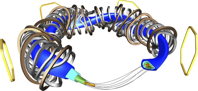
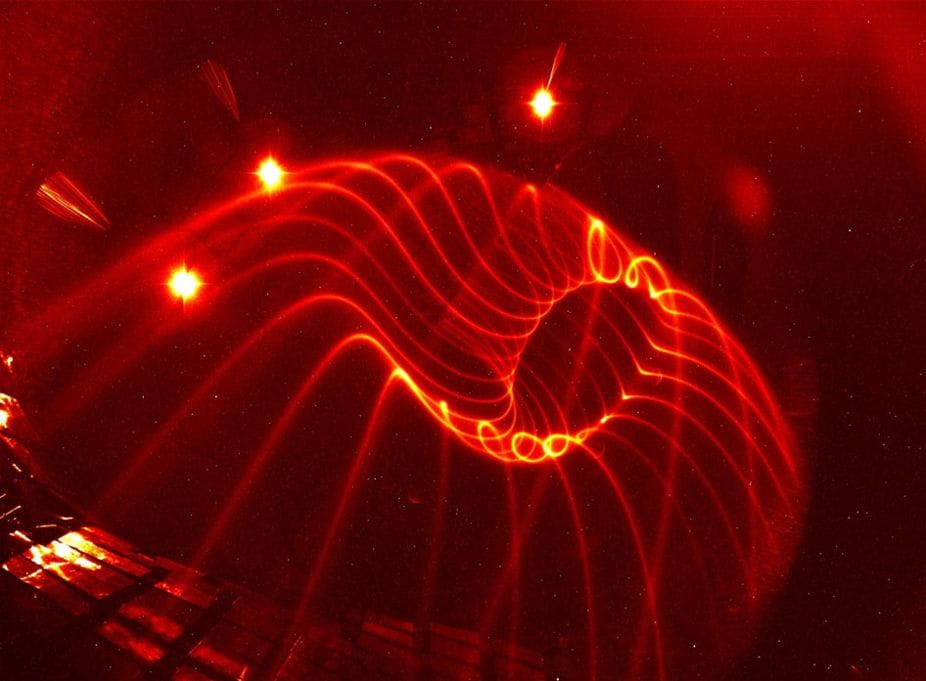
Experimental visualization of the field line on a magnetic surface in Wendelstein 7-X. The field lines making up a magnetic surface are visualized in a dilute neutral gas, in this case primarily water vapour and nitrogen (pn≈10−6mbar). The three bright light spots are overexposed point-like light sources used to calibrate the camera viewing geometry.
 John D
 John D