Helical Piles and Screw Foundations: Capacity, Corrosion, and Cost
Helical piles, ground screws, and adjustable piers: load transfer, torque-to-capacity, corrosion, and cost against concrete.

Screw-Based Foundation Systems: A Technical Briefing
TL;DR
- Screw-based foundations transfer structural load to competent soil through a steel helix in end bearing (plus shaft friction) or through a threaded lead screw bearing on a plate; their defining commercial advantage is real-time capacity verification via installation torque, immediate loading with no concrete cure, and full reversibility, at a higher per-element price than a simple concrete footing.
- The governing field method, the empirical torque correlation Pu = Kt x T (Hoyt and Clemence 1989), is widely codified in ICC-ES AC358 and IBC Section 1810, but it is an empirical correlation with material scatter, not a first-principles result; default Kt values run about 10 ft^-1 for small square shafts down to roughly 3 ft^-1 for large round shafts.
- The technology is mature for light structures, ground-mount solar, boardwalks, and remote sites; the market is a manufacturer-plus-certified-installer model anchored by Hubbell Incorporated (NYSE: HUBB) and populated by numerous privately held specialists and franchisors.
Working definition and scope
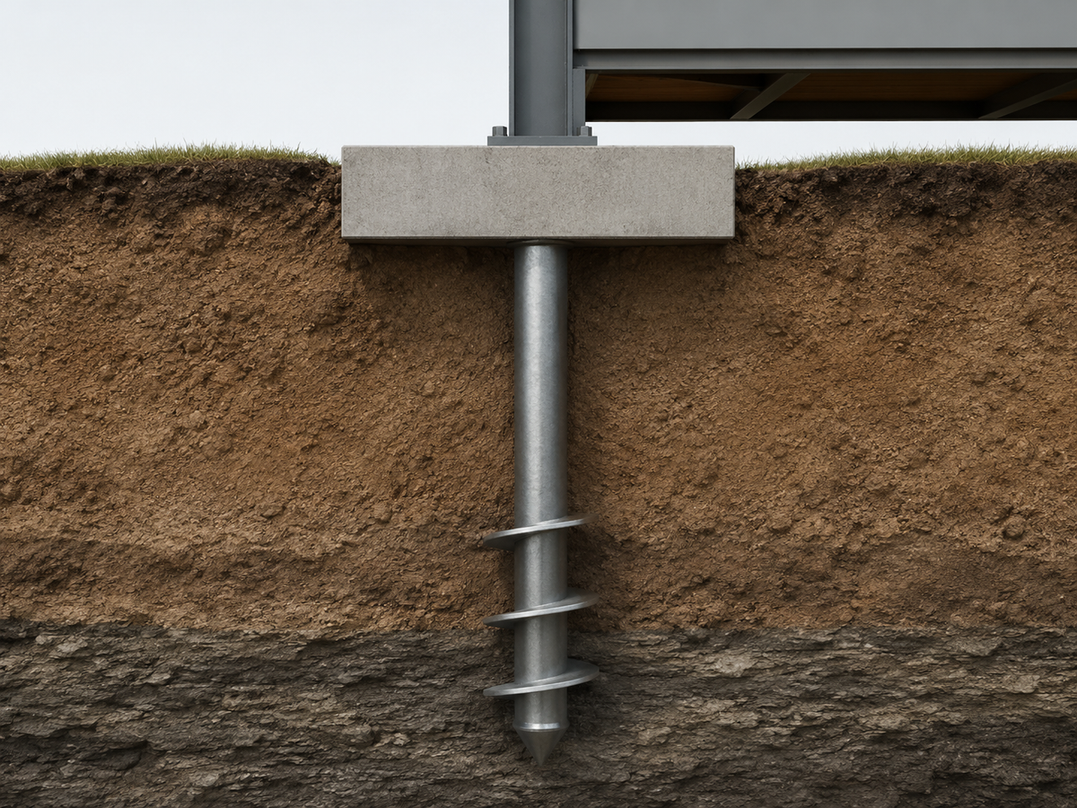
This briefing treats one subject with two embodiments. The first is the screw-in bearing element (helical pile, screw pile, ground screw): a steel shaft carrying one or more helical plates, rotated into the ground so that load transfers through helix end bearing plus shaft friction. The second is the adjustable screw-jack support (lead-screw pier, adjustable foundation jack, releveling jack): a threaded post or jack on which a structure bears, permitting precise leveling at installation and releveling over the service life. The two frequently combine: a ground screw or helical pile is commonly fitted with an adjustable threaded head or saddle, marrying deep load transfer to fine vertical adjustment. Cast-in-place spread footings and conventional driven or bored piles are referenced only for contrast.
Load transfer mechanics
For helical elements, two limit-state models govern geotechnical capacity, distinguished by helix spacing. The individual bearing method applies when helix plates are spaced widely (a common threshold is 2 to 3 times the helix diameter): ultimate capacity is the sum of bearing capacity on each plate (area times ultimate bearing pressure, computed via Terzaghi, Meyerhof, or Hansen/Vesic) plus shaft adhesion above the top plate. The cylindrical shear method applies when plates are closely spaced: the inter-helix soil is assumed to fail as a cylinder, and capacity is the shear resistance over that cylinder plus end bearing on the outer plate. Numerical tools (for example RSPile) compute both and take the governing (lower) mechanism. Shaft friction contributes meaningfully in cohesive and grouted shafts; square shafts contribute little shaft friction but penetrate dense soil efficiently. Helical piles develop broadly comparable capacity in compression and tension, which underlies their use as uplift anchors. For the adjustable screw-jack embodiment, axial load passes through the lead screw in compression to a bearing plate or footing; the threaded interface provides adjustment, not soil capacity, so the supporting element below (a footing, pier, or screw pile) governs geotechnical resistance
Torque-to-capacity correlation
The signature field method correlates installation torque to ultimate axial capacity: Pu = Kt x T, where Pu is ultimate capacity, T is final installation torque, and Kt is the empirical capacity-to-torque factor. This must be labeled an empirical field method with known scatter, not a first-principles result. It originates with Hoyt and Clemence (1989), "Uplift Capacity of Helical Anchors in Soil" (12th ICSMFE), who analyzed 91 multi-helix tension load tests at 24 sites across sand, silt, and clay with shaft sizes from 1.5 to 3.5 inches, and found torque correlation statistically more consistent than the theoretical methods of the day. They established that shaft diameter is the dominant variable, with Kt decreasing as diameter increases. Common pre-AC358 practice used Kt = 10 ft^-1 for square shafts. AC358 (2007) codified default maximum Kt values by shaft size; later editions (2017, 2020) reduced several values (for example, 2.0-inch square shaft to 8.5 ft^-1 and 2.25-inch to 7.5 ft^-1) and added an equation for intermediate sizes. Round/pipe shafts typically run Kt of about 3 to 7 ft^-1, falling toward 3 ft^-1 at 8.625-inch diameter; large-diameter work (Tappenden) reported a single value near 2.8 ft^-1. In SI, square shafts run near 33 m^-1 and round shafts roughly 10 to 25 m^-1.
Per the Hubbell/CHANCE history of the factor, Perko (2009) "developed a formula based on an exponential regression analysis of nearly 260 load tests," subsequently incorporated into AC358; larger databases (CTL|Thompson, over 800 tests) and the Soussi, Cherry and Siller DFI Journal work refined a capacity-to-torque factor accounting for helix configuration and load direction. As Soussi's dissertation states, "Seven hundred ninety-nine (799) full scale load tests in compression and tension were conducted on helical piles of varying shaft sizes, shaft geometry, helix configurations and different soil type (sand clay, and bed rock)"; that work concluded AC358 Kt values underestimate capacity at low torque and overestimate at high torque. Accuracy with calibrated in-line transducers is generally within about 10 to 15 percent of load-test capacity, degrading to 20 percent or more when relying on hydraulic pressure gauges (empirically supported).
Capacity figures
For residential and light-commercial work, manufacturerallowable capacities (incorporating a factor of safety of 2 on torque-correlated ultimate) cluster in the 25 to 55 kip (about 110 to 245 kN) working-load range per pile. Chance Foundation Type RS2875.203 round shaft is rated at 63 kip ultimate and 31.5 kip allowable. Square-shaft ultimate capacities are quoted from about 55 to 200 kip depending on size; Chance Foundation Solutions states its products support "high-capacity new construction applications supporting up to 220,000 pounds per pile." Combination piles span 54 to 147 kip, and grouted displacement/pulldown micropiles reach up to roughly 430 to 450 kip ultimate. Lateral capacity is modest: about 6 kip for shafts up to 4.5 inches, since slender shafts present little projected area. Consumer-grade adjustable helical screws (for decks and sheds) are rated far lower, for example about 5,000 lb in sand and 3,500 lb in clay. Ground screws for solar carry lighter axial loads but emphasize uplift resistance; one ICC-certified ground screw is rated at up to 45 kip compression. Reported projects include residential and light-commercial column loads of 13 to 65 kip; one library-addition project installed 34 piles in a single day to torque-correlated ultimate capacities at least twice the working load. Static load testing per ASTM D1143 to 200 percent of design load remains the definitive measured verification.
Soil suitability and failure modes
Screw foundations excel where they can bypass weak upper strata to reach competent bearing. In expansive/swelling clay, square-shaft helical piles are a long-standing practice; per Cannon, "Performance of Square Shaft Helical Pier Foundations in Swelling Soils" (ASCE Geo-Volution),
"Since 1986 it is estimated approximately 130,000 square shaft helical piers...have been installed for both remedial repair and foundations for new construction in swelling soils, including the highly expansive steeply dipping bedrock areas of the Front Range. There are no documented failures."
The helices are anchored below the active (seasonal moisture change) zone to resist uplift. In frost-susceptible soils, helices must terminate below the frost line (varying from about 36 inches in temperate zones to over 48 inches in northern regions) to prevent frost heave and adfreeze uplift on the shaft. Uncontrolled fill containing rubble, brick, and rebar damages helix plates and produces erratic torque. Cobbles, boulders, and rock cause installation refusal (torque refusal); square shafts penetrate dense material better than pipe shafts, and pile locations are sometimes shifted to clear obstructions. In liquefiable, organic, or peat soils the principal risk is shaft buckling: slender shafts lose lateral soil confinement, so pipe shafts, combo piles, or grouted displacement piles are specified, and capacity ratings assume continuous lateral confinement (SPT N >= 4). High water tables reduce soil strength and impose buoyancy on the shaft.
Corrosion and service life
Service-life figures are derived by back-calculating the time for a defined corrosion loss. AC358 prescribes scheduled steel-thickness losses over a 50-year design period for bare steel; capacity ratings typically embed this allowance, and because the steel needed to generate installation torque generally exceeds that needed to resist service loads, corrosion rarely governs design. Hot-dip galvanizing per ASTM A123 (hardware per A153) adds a zinc barrier; Chance products average 4 mils of zinc, modeled to yield service life exceeding 50 years (galvanized zinc corrodes at roughly 1/30 the rate of bare steel). ASTM A123 sets minimum coating thickness (for example, at least 3.9 mils on steel 1/4 inch and thicker), with no maximum. Magnum Piering catalogs a 75-year design lifespan based on a 50-mil corrosion loss, extendable about 16 years by epoxy powder coating or more than doubled by galvanizing. AC358 defines corrosive soils as resistivity below 1,000 ohm-cm, pH below 5.5, high organic content, sulfates above 1,000 ppm, landfill, or mine waste; chloride exposure (marine, de-icing salt) accelerates loss. Large-diameter piles often rely on sacrificial steel thickness rather than coating. ISO 12944 (coatings) and AS 2159 (Australian piling) provide analogous frameworks abroad.
Standards and acceptance
In the United States, ICC-ES AC358 (Acceptance Criteria for Helical Pile Systems and Devices) is the governing evaluation document; products earn an ICC-ES evaluation report (ESR) recognized under the IBC. IBC Section 1810 (Chapter 18) covers deep foundations, with Section 1810.3.3.1.9 specifically permitting helical-pile allowable load determination by the lesser of soil bearing, torque correlation, or load test, and 1810.2.1 addressing lateral support and buckling. AC358 also adopts the Modified Davisson interpretation (failure at net deflection of 10 percent of average helix diameter). In Canada, the Canadian Construction Materials Centre (CCMC) issues evaluations referencing CSA steel standards (G40.20/G40.21) and conditions on registered-engineer approval, welding, corrosion protection, and certified installers under the National Building Code framework. In Europe, design follows Eurocode 7 (EN 1997) with CE marking and EN ISO product standards. Permissibility frequently hinges on whether a specific product holds a current evaluation report, a material competitive fact.
Economics Cost figures are a mix of reported project and manufacturer ranges and vary widely with load, depth, and access. For decks and light structures, per-pile installed costs are reported around $250 (Rise) to a few hundred dollars (Techno Metal Post); one repair-oriented source cites about $175 per pier with multiple piers per location. For light-to-mid-scale buildings, retrofits, and underpinning, installed costs are reported at $2,000 to $4,000 per pile (TorcSill). The decisive economics are schedule and avoided scope: helical piles carry full design load immediately, versus concrete reaching roughly 70 percent strength at 7 days and full strength at about 28 days. Installation is fast, with reported rates up to about 20 piles per day and project examples of 34 piles in one day; a single-family home foundation can be installed in one to two days. Equipment scales from handheld and crawl-space units (around 6,000 ft-lb) through skid-steer and mini-excavator drive heads (12,000 to 20,000 ft-lb) to large excavator-mounted heads exceeding 300,000 ft-lb; drives run at a controlled 10 to 20 RPM. Crews are small and mobilization light. Helical piles tend to be cost-competitive on poor or variable soils, constrained access, cold or wet weather, and tight schedules, and less competitive than a simple spread footing on good soil with easy concrete access.
Embodied carbon and reversibility Carbon comparisons are modeled, and the direction of the result depends on scope. A Hubbell/CHANCE analysis using the EFFC-DFI Carbon Calculator V4 for a streetlight pole base reported "a potential carbon impact span from 1.4 ton to 0.8 ton carbon dioxide equivalent (CO2e) depending on the technology selected" (concrete versus steel helical), driven mainly by freight, since "One of the largest Chance foundations for pole bases weighs only 404 pounds. A comparable concrete base could weigh over 10,000 pounds". Conversely, a peer-reviewed optimisation study (Abushama, Hawkins, Pelecanos and Ibell 2025, Developments in the Built Environment) found that steel piles generally carry higher embodied carbon than concrete or timber structural piles on a material-optimised cradle-to-gate basis, with timber lowest; that study did not analyze helical screw piles specifically. The reconciliation is scope: steel's advantage in the streetlight case comes from low mass and avoided freight, whereas heavy structural steel piles carry steel's high per-kilogram carbon. For context, normal reinforced concrete embodies on the order of 300 to 400 kgCO2e per cubic metre (cradle-to-gate, OPC) with cement near 0.9 kg CO2 per kg. No field-measured LCA specific to helical-versus-concrete light foundations was identified. Reversibility is a genuine differentiator: steel screw elements can be unscrewed and extracted, and Chance reports foundations removed and reused after 25 years, supporting temporary, phased, and modular applications.
Market structure and players
The dominant commercial model is manufacturer-plus-certified-installer: a manufacturer supplies engineered shafts, helices, brackets, and design support, while a trained or franchised installer performs torque-monitored installation. The confirmed public anchor is Hubbell Incorporated (NYSE: HUBB), whose Hubbell Power Systems unit markets the CHANCE helical foundation line (the A.B. Chance brand dates to 1907, with deep-foundation manufacturing since 1912); Hubbell reported net sales of $4.1 billion in 2021 per its FY2021 Form 10-K, of which foundations are a small part. Other helical-pile manufacturers and installers are privately held, including Ram Jack (Ada, Oklahoma, founded 1968), Magnum Piering, IDEAL Foundation Systems (IDEAL Group), and PierTech Systems in the United States, and the Canadian franchisors GoliathTech, Postech Screw Piles (since 1995), and Techno Metal Post. GoliathTech (Magog, Quebec) is listed by Franchise Direct's FDD profile at an estimated 165 units, and FranchiseGrade's 2025 FDD data states there are 107 franchised GoliathTech locations in the USA across 31 states. Ground-screw specialists include the privately held German firm Krinner (with U.S. solar-market activity), Stop Digging, and American Ground Screw; adjustable consumer products include Pylex (sold through major retailers). Solar-sector integrators such as Terrasmart and APA Solar deploy ground screws and driven piles at utility scale.
Outlook
On current evidence, screw-based foundations are an established, code-recognized choice for light structures, ground-mount solar, boardwalks, manufactured/modular housing, and remote or access-constrained sites, where their speed, real-time torque verification, reversibility, and all-weather installation are decisive. Their cost premium over a simple footing is generally justified by avoided excavation, avoided cure time, and reduced schedule risk on difficult soils, and is harder to justify on good soil with easy concrete access. The most consequential open question is standardization of torque correlation for large-diameter shafts beyond the current AC358 range, where load-test data remain comparatively thin; refinement of capacity-to-torque factors (the Soussi, Cherry and Siller direction) is the area to watch. This outlook assumes continued code recognition and steel-price stability, and would shift if independent life-cycle assessment overturned the manufacturer-favorable carbon narrative for structural (as opposed to lightweight) applications.
References
- Hoyt, R. M., and S. P. Clemence. 1989. "Uplift Capacity of Helical Anchors in Soil." Proceedings of the 12th International Conference on Soil Mechanics and Foundation Engineering, Rio de Janeiro, Vol. 2, 1019-1022.
- Perko, H. A. 2009. Helical Piles: A Practical Guide to Design and Installation. Hoboken, NJ: John Wiley and Sons.
- ICC Evaluation Service. AC358 Acceptance Criteria for Helical Pile Systems and Devices.
- International Code Council. International Building Code, Chapter 18, Section 1810.
- Soussi, M., J. A. Cherry, and T. Siller. 2020. "Helical Pile Capacity-to-Torque Correlation: A More Reliable Capacity-to-Torque Factor Based on Full Scale Load Tests." DFI Journal 14 (2); and M. Soussi, PhD dissertation, Colorado State University.
- Hubbell Power Systems (CHANCE). Technical Design Manual; "Origin and Development of the Torque Correlation (Kt) Factor"; and "Carbon Impact of Helical Pile Foundations vs Concrete Foundations."
- ASTM A123/A123M, Standard Specification for Zinc (Hot-Dip Galvanized) Coatings on Iron and Steel Products.
- Abushama, K., W. Hawkins, L. Pelecanos, and T. Ibell. 2025. "Optimisation of Embodied Carbon and Construction Cost of Concrete, Steel and Timber Piles." Developments in the Built Environment 22: 100656.
- Hubbell Incorporated. FY2021 Form 10-K and related SEC filings (Forms 10-K and 8-K).
- National Research Council Canada, Canadian Construction Materials Centre (CCMC) evaluations and technical bulletins.
- Cannon, J. "Performance of Square Shaft Helical Pier Foundations in Swelling Soils." ASCE Geo-Volution.
- Hammond, G., and C. Jones. Inventory of Carbon and Energy (ICE) Database, Circular Ecology.